Modela PCB
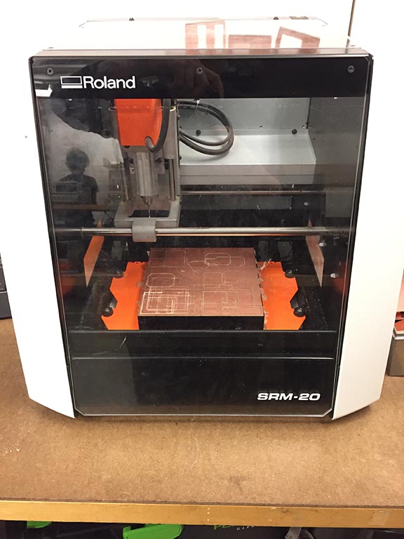
We have 2 Modelas in 3-402A - an older MDX-20,
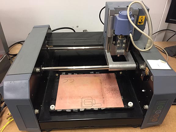
and an SRM-20.
There are a few things we need to pay close attention to with these machines when cutting copper board -
a very flat and clean spoilboard, so your copper board can also be taped perfectly flat, so it is in
the exact same XY plane with no gap underneath - clean, flat board layers that were taped down very flat, very carefully,
are super important
the amount of travel room the Z axis has on its 2 vertical rails,
and the distance from the collet/tool and the board underneath.
You need to make sure you jog the tool around at a safe distance from the board while setting up,
and also make sure you leave enough Z travel doing down (moving in negative Z) so that the
tool can reach the cut depths it's going to be told to go to. The cut depths for PCB work is
pretty shallow, but it's still not uncommon to accidentally bottom out on the Z rails.
The mods/machine will not warn you that this will happen - it will happily bottom out and
continue moving around in XY, at the wrong Z.
This isn't really an issue - operators just need to be aware of the window of Z height
within which we need to work, and stay
inside it.
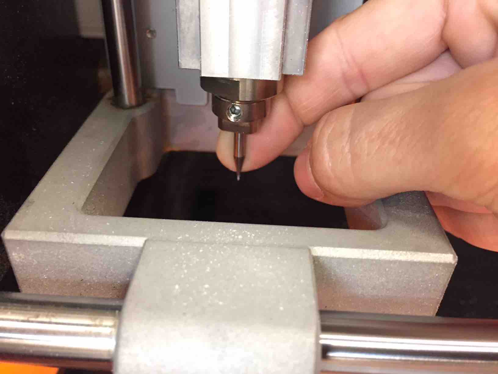
Note the limited travel in Z in the photo below - the spindle rides on the 2 vertical rails, which in this photo,
have only a little over 1mm left to move above that horizontal plate (upper highlighted box) if jogged down in Z.
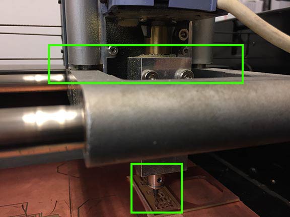
In the lower highlighted box is the collet, the too holder, as close to the board (in this example) as it can
reasonably get. Once the Z axis is jogged close enough to the bed for one of these short end mills to be properly installed
(you want to minimize this distance), there is not a lot of wiggle room left for safe jogging distance in Z (this is fine -
just make sure you're conscious of the very limited Z distance to work within).
When jogging around in X/Y, you need to repeatedly make sure that the tool will not collide with anything else. There's no need to try to get
really close to the board until you are at the XY zero you want, and are ready to set the final coordinate - Z location.
Remove an installed endmill before moving, or install it inserted high up into the collet (like in the above photo).
The board can be taped anywhere on the spoilboard - choose a location that is clean, flat, and doesn't have any bumpy bits
on it from previous cuts or tape debris. If the spoilboard needs cleaning, you can wipe it with alcohol (use laser cutter lens
spray bottles) and a paper towel - make sure no paper fibers are left on the plate. To remove minor burrs from previous cuts, try using
the edge of your copper board gently as a scraper, or ask shop staff for help. Once the spoil boards are really chewed up, we
will replace them.
When you move the spindle to the XYZ zero that you want to set as your job origin, you need to have left enough negative Z
movement on those vertical rails so it can still lower itself just a bit more to cut (for PCB tracing, this will be less than 1 mm).
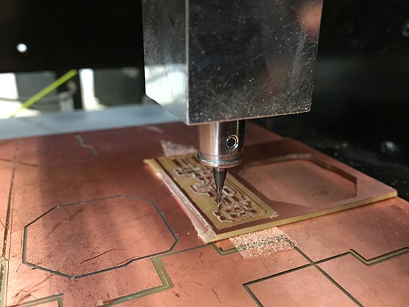
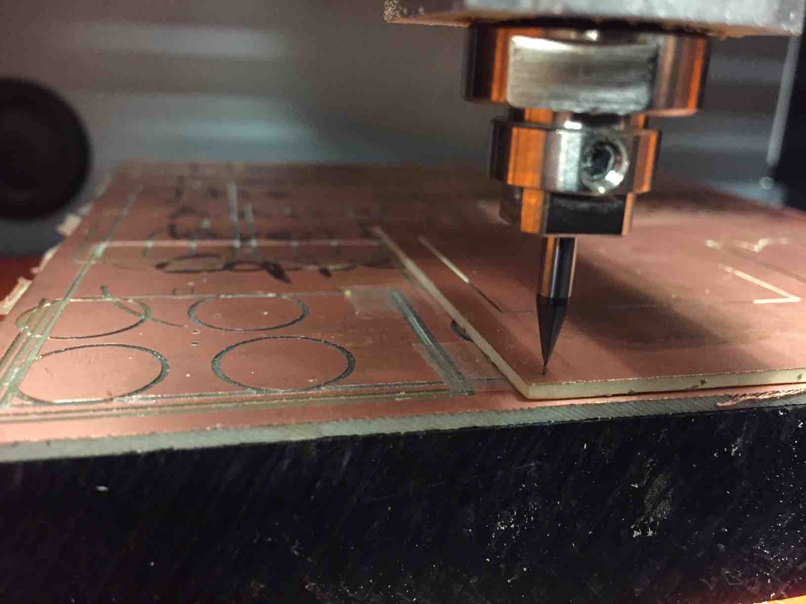
In the next image, the end mill is inserted well into the collet - be conscious of setting your Z location up so you are inserting the
tool as much as reasonably possible, just like this. All cutting tools like this, whether CNC or manually operated, should be as short
as possible and always inserted fully, so the interior of the tool holder has a sufficient grip on the tool.
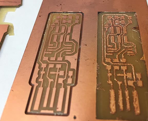
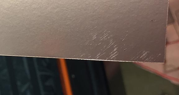
The image below shows a clean cut on one side, and a messy cut on the other. This was probably caused by using a chipped/broken
end mill, or possibly a poorly installed end mill.
The board you will cut must be very carefully attached, as absolutely flat as possible, with clean, unwrinkled tape - onto a clean
spoil board with absolutely no wrinkles, burrs, dust,
or other mess that can bump it up out of parallel with the spoil board.
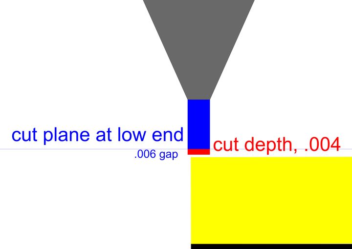
The cut plane will not be parallel to the board if the material
is not, and it can cut too deep in places, or float outside of the material entirely, depending on where on the bad surface
you've set your Z zero. In this next photo, Z zero was set at the tip of the end mill on a high spot, and as it moved in the
horizontal cut plane, with the board sloping down, the tool ended up floating above, barely scraping/burnishing the surface as
that copper surface sloped too low for it to reach.
These graphics illustrate how this can happen with a bit of junk just .01" in diameter, with our PCB cut depths of .004".
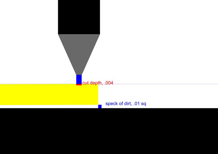
The change in Z height @ the tip of the end mill is across a horizontal distance of just under 4 inches, which can easily
be travelled within the area of a Modela's bed.
We cannot just edit cut depth to try to fix this - these 1/64" end mills have tiny (.03") flute lengths, and can't necessarily just be
pushed deeper - it will cause a collision of a non-cutting edge with the material, that will break the end mill and could even rip
the board from the machine bed.
Always use the default cut depths on the mods for cutting traces/outlines, and if there's an issue with it, we have to diagnose
the problem without trying to alter the defaults, which have been thoroughly tested for this work.
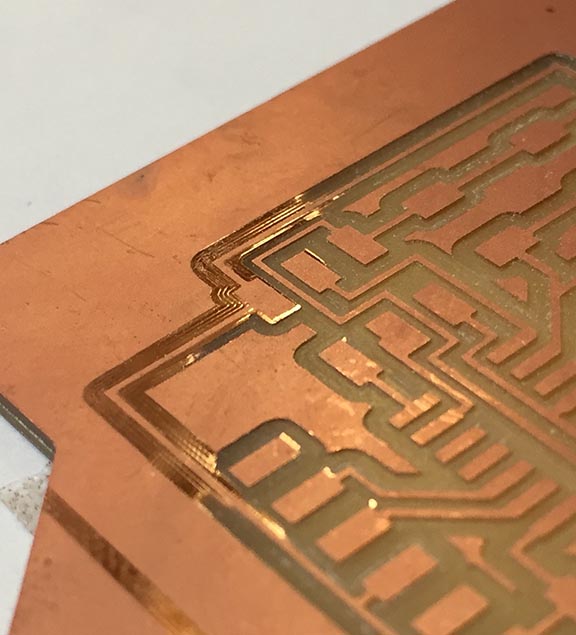
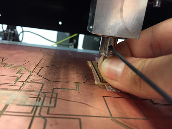
The copper boards can have burrs on their edges from being cut, or rough handling - it's visible in this photo. You have to be
aware of little details like this on any surfaces that you will be referencing and/or adhering to another. Burrs like this
will create gaps between boards and boards, and boards and end mills. You wouldn't want to try to tape a copper board to the
Modela's spoil board with one of these rough edges bumping it up off the surface.
They're small, but the thickness of a burr like this edge becomes significant on the scale of circuit boards.
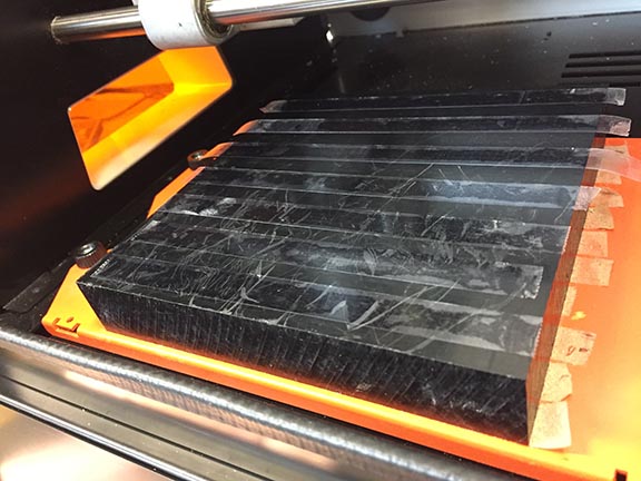
This is the tape underneath a new spoil board being installed on the MDX-20. It looks messy, but it was carefully wiped down and scraped
flat, and the tape was very carefully laid down to ensure a flat spoil board.
In the same way, when you attach your boards to the spoil
boards, these surfaces must be completely clean, and the tape must be flat and clean, for the surfaces to remain parallel to the
cut plane of the spindle in its XY travel.
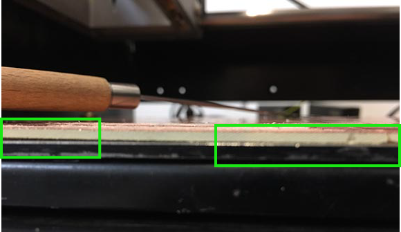
This next photo shows the edge of a spoil board lifting up off of the plate below - you must notice when these things happen, or your work will
likely fail. Check the spoil boards to make sure they're flat and clean before use, as well as the upper layer you make with
your own board. If the tape just came loose, press it flat again (and make sure it sticks).
Please alert shop staff/ TAs when spoil boards are chewed up enough to need replacing, or
warped and refusing to lay flat - and let us replace them for you, whenever possible. It is crucial that they get installed correctly for
any subsequent jobs to be successful.
Dust and debris getting in the way of a clean flat tape job is a common issue - these machines make PCB shavings/dust when they cut, and
the edges of the cuts on the spoilboard can have burrs, like tiny ridges, left behind as well.
All users are expected to vacuum up their dust, and
remove all used tape to leave a clean surface for the next user.
All used tape and trash boards must go immediately into trash - do not leave any garbage on the tabletops.
When a user wants to tape a board down, they must check the spoil board and clean up any mess first, no matter how minor it might seem. Check
for tiny invisible burrs as well as for dust - you may not be able to see it, but that doesn't mean it isn't there.
Check the boards and make sure they are actually flat, as well. If you use a larger board, it's more likely to be a potato chip, which
will not want to lay obediently flat. They can be coaxed somewhat, by gently flexing in the opposite direction of the curve - but be careful
if you try this - and don't expect change caused by the flexing to last for too long - they will want to relax back into their previous
shape, eventually. Cutting boards into smaller areas is a better option to deal with warping. Tiling smaller boards makes for more stable
spoilboards, as well.
The screenshots below are from SRM setup (MDX is similar - see end for additional MDX info).
Double-click on the Terminal desktop icon to open the connection to the machine. This icon is just a shortcut created to do a few
steps for you, which you can read about here:
SETTING UP MODS IN LINUX
If the terminal desktop shortcut doesn't work, you can open the connection without it - it's just a convenience that opens a terminal window and
runs a command that you can do yourself -
(taken directly from regerohan's 'setting up mods in Linux' page) -
Open a terminal window in the 'js' folder (in Linux just right-click anywhere on the space (not on a file) in /mods/js and open a terminal window there), and type -
node deviceserver.js 127.0.0.1 1234
or
node deviceserver.js ::ffff:127.0.0.1 1234
IPv6 is preferred
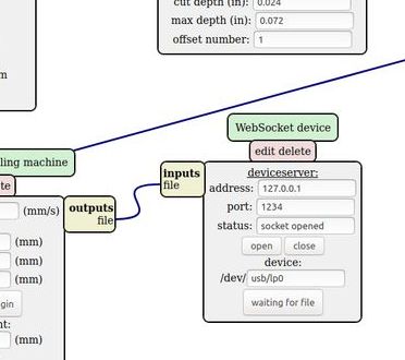
Click on the open button on the device module, the port is opened.
Checking the terminal, we can see that an incomming connection is accepted.
If you get an error, you can try using the IPv6 address (::ffff:127.0.0.1).
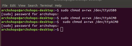
Or if it is a permissions issue-related error, try this first -
sudo chmod a+rwx /dev/ttyUSB0
(or /dev/lp0, lp1, lp2... whichever connection the machine is currently on)
The password is the same as the username (just read your terminal command line for a reminder)
That setting is meant to be permanently added, but it hasn't been sticking after restarts, so if you can't connect, do try it.
The window should stay open and say "listening for connection".
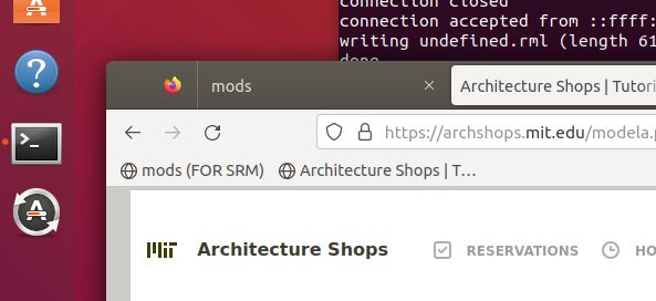
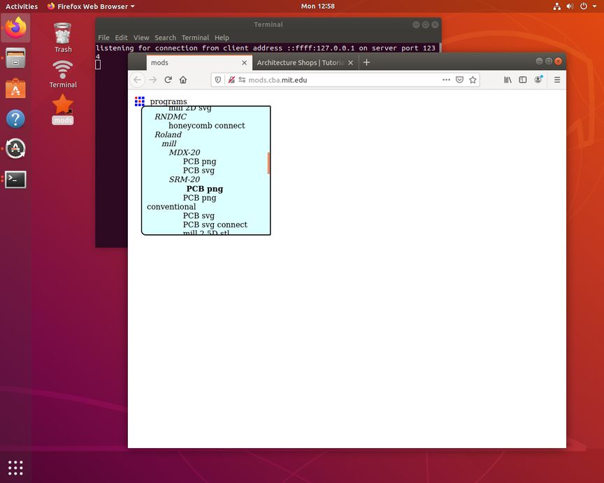
To open the mods page, use the bookmark saved in Firefox (mods (FOR SRM) ).
Don't use mods.cba.mit.edu- that version doesn't work on either of our Modelas.
Right-click on CBA icon - choose programs -> server program -> Roland Mill -> SRM 20 -> pcb png
The next screenshot shows the steps to take to set up a file to send to the SRM 20.
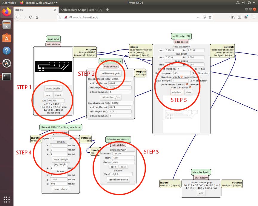 1
1 - open your black & white PNG (check the scale, confirm that it is the correct size. Changing the dpi in this module will change
the output size).
2 - choose the type of cut - for PCB production, you're choosing between traces and outline. Traces cut very shallow, just to remove
the copper.
Outline cuts all the way through the board. We need to make sure we do traces first, keeping track of the (relative) origin coordinates, and then
go back, open up the outline png, and this time
choose 'mill outline' for step 2, and install a 1/32" end mill before setting new Z location at the same XY origin and calculating.
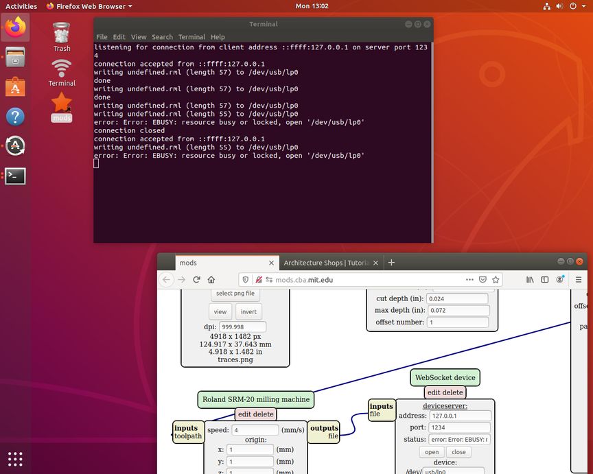
3 - confirm that the status is "open". The terminal window must be "listening for connection" in order for this to work. If you
cannot get it to open here,
check the /dev folder to make sure that the device matches (lp0, lp1...). The port listed in mods just needs to match.
If permission is denied, open a terminal (on desktop is fine) and
type
sudo chmod a+rwx /dev/usb/ ...lp0, lp1 or whichever port it's on).
If you need to do this, just right-click on the desktop to open a terminal window.
Password is the same as the username - look at the command line in your terminal window for a reminder.
Note that a freshly opened terminal window will not
automatically function like the special "terminal" icon shortcuts. As noted above, follow instructions for manually opening connection if the
'terminal' desktop shortcut isn't functioning (they glitch out on rare occasions).
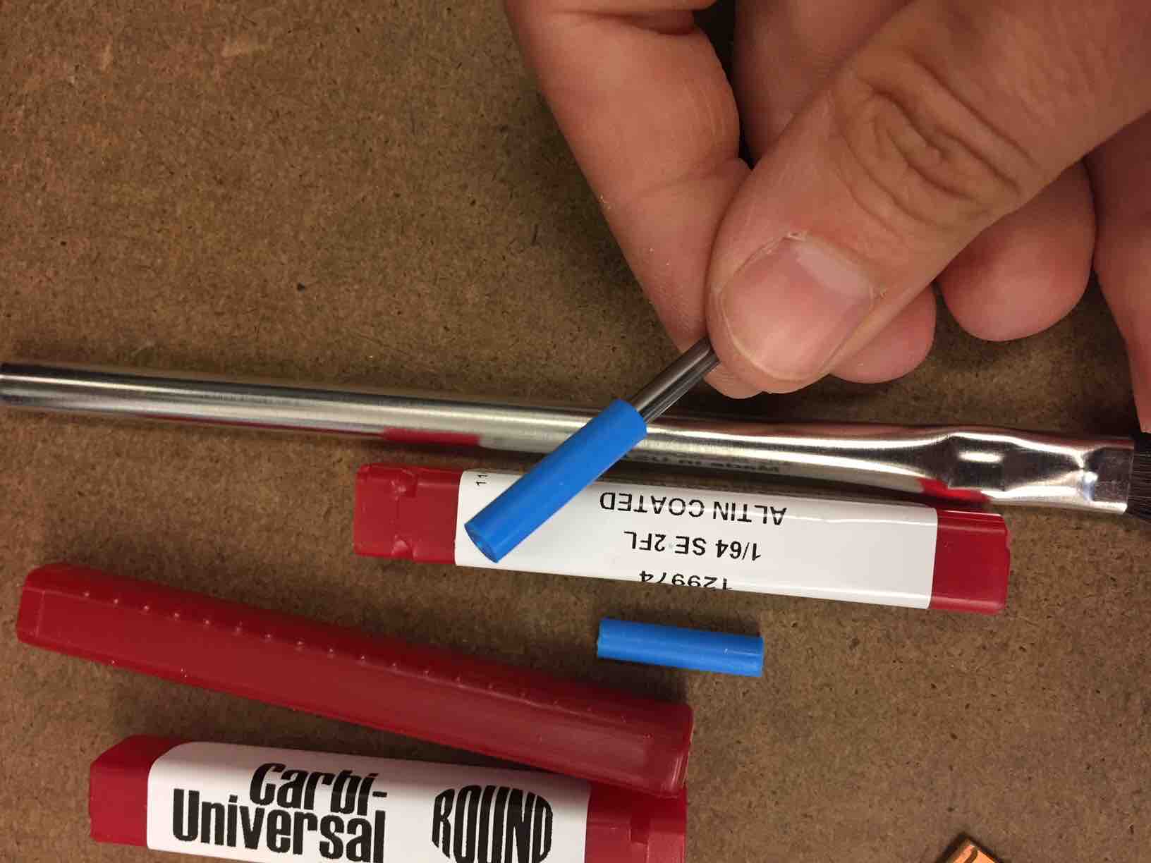
End Mills
The end mills we'll be using are tiny, and absurdly easy to break. You will have gotten training on this- you
must
keep the blue covers on and the end mills in the red containers
(in the wall cabinet)
whenever they are not actively in use. If they fall on the floor, they WILL break.
 4
4 - If an end mill is installed, make sure it is far up in the collet to prevent potential crashing when you're jogging around in X/Y.
Make sure the SRM is on, and that the power button (top of machine) is green,
but NOT blinking. Restart if blinking. The machine will only allow jogging when the front cover is CLOSED. You'll be forced to restart
if you attempt to jog with it open.
Use the "origin" coordinates to move in X and Y first, and find the corner of your copper board. If you have not taped one down yet, do it now.
Leave the jog height at 2 (default)
Once you're in an X/Y spot that you think is good, you'll need to move the spindle in Z to comfortably reach the collet with your hands, a hex key, and
the end mill. This might be up high or down low - depends on your preferences. Don't forget you need to do this with the lid down!
The end mill, once installed, might make it easier to see that your X/Y needs a little more adjusting to get close to the corner. Try not to waste
material by leaving excessive margins, whenever possible. Multiple boards can usually be cut from one piece of material - do your best to conserve it.
When you are in the ideal X/Y spot, with the endmill installed, move carefully down in Z to get close, while still leaving a little
negative Z movement free for cut depths. On the SRM (orange machine), move to Z 1 (
only after finding a good XY location). Then from there manually drop the end mill to the copper surface.
Tools for the SRM are in its bottom drawer (under the bed).
Tools for the MDX are in the little part cabinet on the wall.
We need to minimize how much the end mill sticks out of the collet, while still allowing the whole Z axis enough negative movement
(will be less than a few mm) to
cut your job. The end mill should be inserted high in the collet, just as in the above photos, for safe jogging.
To finish setting Z location, loosen the set screw, let the end mill descend the short distance to rest on the board- and grab and gently press
press the tip of the end mill into the copper manually, as in this photo, while you retighten
the set screw.
The end mill should not have far to drop to rest on the board.
Loosening and dropping the end mill a few mm to meet the board at XY zero is what sets your Z zero location. The coordinates that the mods
displays on the screen when you do this will become your job's origin when you 'calculate' the file. This is all you need to do to set
that origin. But again, when you're setting Z by bringing that tool tip to the copper surface, with the collet's set screw loose, grab and
gently press the tool tip into the surface of the copper while retightening the set screw - if you don't press it in just slightly like
this, we've noticed that it will be much more likely to float or drag just at the surface of the copper, and not actually cut to the correct depth.
5 - You can see what the default cut depths are in the mill/raster/2D module (for traces, it's .004") - do NOT change these settings
under normal circumstances. If there is an issue with cut depth, it will almost always be because the board/spoil board aren't taped down clean
and flat on the machine.
If you want to cut away all the excess copper from your board, you can change the offset number in this module to 0 (where it says 0 = fill).
Four outlines is the default - it should remove enough of a border so you can solder without accidentally creating bridges that will cause
shorts. Cutting all
the copper away takes longer, but some prefer to do it anyway. Remember that you can edit your b&w images to keep/remove any copper that
you'd like,
and are not stuck just using the image created by the software (Kicad/Eagle) that you used to draw it, as-is.
Once your settings are good, AND your end mill is set and tightened at X Y Z zero, only then can you click the "calculate" button.
If you go back to make any changes at all, you need to get everything set and calculate again.
After calculating, you're almost done- the module circled in "step 3" has a button that will now say "send file to device".
"send file to device" will send the job to the machine, which will automatically start cutting, assuming the connection is still open.
When done, put scrap (IF USABLE) boards into the metal box - and clean up ALL USED TAPE - PUT IT IN THE TRASH BIN.
We've had a lot of issues with users leaving tape all over the countertops - please do not do this. It becomes a big mess and is
absolutely not easy to clean up.
Before you walk away, make sure you've left nothing out on the countertops - all tools need to go back into their part drawers.
Remove all tape from all objects before leaving - do NOT leave any on scrap or machine or table. Vacuum all dust, give damaged end mills
to shop staff or TAs - post an issue so we know to refill replacements.
MDX-Specific differences
The SRM is a newer version of the MDX - they both work perfectly well, but there are a few differences.
The cover on the MDX has been removed - you must wear safety glasses while operating this machine.
There are Z up/down buttons on the front of the machine - instead of jogging in Z on the computer, use these to move in Z. They're not
super-sensitive, so expect to push firmly and also to hold them down and wait for a moment before the machine responds.
The 'view' button will move the bed forward so you can see/work on it more easily - but you have to get out of 'view' mode to jog to your
origin,
which is where you need to be to start running the gcode, as well. So keep an eye on these buttons. You have to bend down to eye level for the LEDS
to really be visible.
The power button is also here - restart
if you
have any trouble with the connection.
There is a local html page linked on the desktop - we need to use this for mods setup on the MDX.
You will still use the mods to jog the machine in X and Y.
If the connection is interrupted, powering down and waiting a minute before restarting the MDX (or restarting a couple of times)
may be necessary to clear out the previous interrupted job and start fresh.
Make sure on the MDX that you have "serial server" open - you might accidentally click on the 'device' section below on this module.
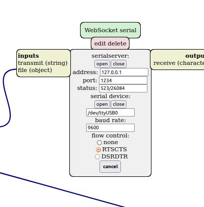
As with the others, if permission is denied, open a terminal (off desktop is fine) and sudo chmod a+rwx /dev/ttyUSB0 (or whichever port you are using)
 RESERVATIONS
 HOURS
HOURS TUTORIALS