Intelitek Super Prolight 1000
THESE MACHINE TUTORIAL PAGES ARE NOT A SUBSTITUTE FOR MACHINE TRAINING AND PRACTICE - THEY ARE MEANT AS A BACKUP REFERENCE
ONLY. ALL SHOP USERS MUST GET ADEQUATE MACHINE TRAINING IN OUR SPACES TO OPERATE ANY MACHINERY OR POWER TOOLS
INTELITEK INSTRUCTIONS
This tutorial is referencing the 4.140 wax milling assignment, so the machinable wax is frequently referenced. In general, operation
for other materials is the same - but fixturing may need to be different. Work this out with shop staff at the beginning of planning
a job on this machine.
- Swipe card to activate machine power (authorized student/shop staff must be present)
- Make sure Dell Precision T1600 on table is on (no logon or password needed)
- Turn Intelitek controller power on (red switch on left of black controller cabinet underneath mill table)
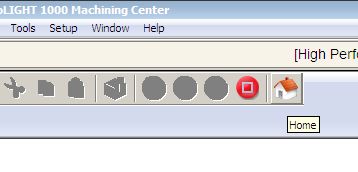
- Start 'CNCBase for intelitek CNC' if not running already Home machine (hit CTRL H on keyboard, click on 'Home')
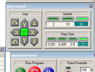
 Jog Buttons -
Note the continuous vs. incremental jog buttons (and speeds) - you'll need to use the small increments to comfortably jog to X/Y zero, and
also to set your Z zero - be very careful when jogging the tool near any object (stock/spoilboard)- never risk crashing into anything!
The spoil board is marked with limits for X/Y, with some reference lines to make alignment easier - put the wax block parallel
to, and inside the margins.
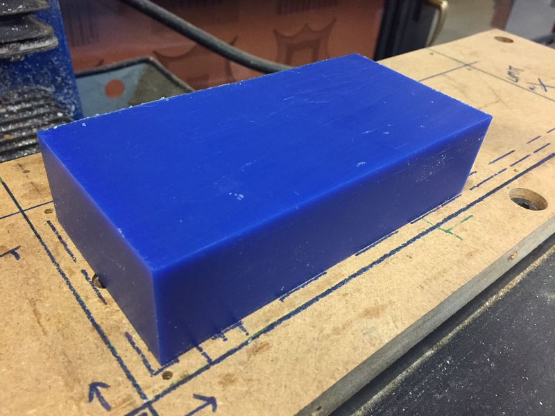
The best way to fixture these wax blocks to the Intelitek or Shopbot MDF spoil board is hot glue. Run a bead around 40-50%
of the edge - good glue adhesion to the wax and also with the MDF bed is necessary. If your bed doesn't thoroughly spread on
both, go over it again.
Do not put glue under the block - just run a good bead around about 60-70% of the outside edge -
the key is to make
sure it spreads fully on the side of the wax AND on the MDF. It won't work if it's just a plastic worm lightly touching those faces.
As long as you do that, you don't need to use a lot of glue - remember that you'll need to pry it off the
bed and scrap off all the excess hot glue, afterwards. Do not put glue underneath the wax block!
By this point, you should have a Mastercam file set up for the Intelitek, with tool info edited to match the little library
on the table - and
you MUST have an authorized shop monitor/staff person check and approve your file to convert to Gcode.
Create separate gcode files for each tool (you can group multiples together if they use the same tool - be careful of issues
that may be caused by shuffled cut order, though)
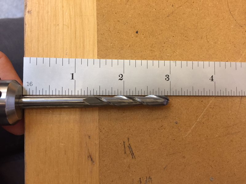
You'll see that most of the tools set up for the Intelitek are small, and shorter than tools set up on the Onsrud tool changer -
though they are mostly the same range of diameters (.125", .25", .375", .5")
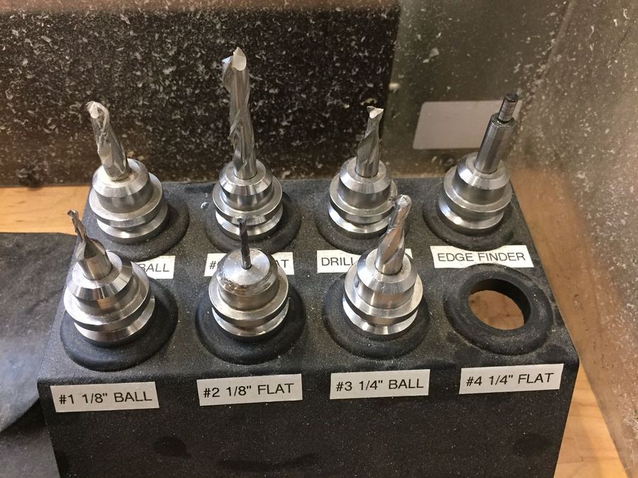
Some of these tools, however, do have wider diameter shoulders/shanks than their diameters along the cutting edge (flute).
Make sure you take those into account if you use these tools, that the tools in the Mastercam setup match
exactly, so the
preview can show any collisions that might be caused by these tool shapes.
The tools in the Intelitek library tooldb file should match the set on the table - but you must always double-check that your
chosen tools match exactly, before and during the job (if you have more than one tool to use, and will need to change out tools
between files).
 If there are any differences between the intelitek tooldb file and the actual tool library setup on the table, first, make sure your file
setup matches reality before you attempt to cut anything - and also send archshops a note just to make sure we're aware that something
has been changed, so we can do any necessary updating.
If there are any differences between the intelitek tooldb file and the actual tool library setup on the table, first, make sure your file
setup matches reality before you attempt to cut anything - and also send archshops a note just to make sure we're aware that something
has been changed, so we can do any necessary updating.
The Intelitek's tool library file for Mastercam setup has some generic feeds & speeds set up like the Onsrud tooldb - check with
shop staff on these numbers to make sure they are appropriate for the work you are doing (this is a normal part of good CAM
file setup- we have defaults set on the Onsrud tools that often need adjusting).
There are chip load charts on the website pages for the Shopbot and Onsrud - they are not actually machine-specific, but
tool/material-specific.
Any plain carbide end mill of a certain diameter spinning at a certain rpm, and traveling at a certain feed rate, will cut
a specific chip thickness. Different materials (like wax vs MDF vs aluminum vs solid maple) have different ranges of good
chip load(this also shifts depending on whether the tool is made from carbide or high-speed steel)
Use the chip load calculators to find good feeds/speeds for the tool, update the Mastercam file, and ask the shop staff
person to check these numbers.
The Intelitek has a maximum RPM of 5000
These machines also have limits to how fast they can move, in X/Y, within the enclosed bed area. Think of them like sports
cars in parking lots. You can tell the machine to move 400 inches per minute in X/Y, and it might not explicitly refuse,
but that doesn't mean it will actually get up to those speeds in reality. Good chip load is crucial to good cut results -
and the numbers are proportional to each other. So the problem with numbers that are out of proportion to the machine's
ability and what the material wants are that if the feed rate (movement in X/Y) and the spindle speed aren't in sync, the
cutting flutes won't be properly rotating with the rhythm needed to cut that correct-thickness chip out with each revolution.
So know the spindle speed (rpm) ability of the machine you intend to use, check the defaults we have in the tool libraries if
they exist (the Shopbot doesn't have one preset), and ask for help determining something reasonable for what you're trying to do.
The Shopbot is a good example for this - it has a spindle capable of spinning at 18000 rpm. But the bed itself is tiny - only
24x48 inches. So even if we were to attempt a good/fast chip load set up for a typical material like plywood, if we set the
spindle at a starting point at one end, got it spinning at 18k, and then told it to travel as fast as it possibly could in Y
up the bed 48 inches, it still wouldn't really be able to keep up with itself. this is like that sports car in the parking lot
spinning out, burning up the wheels.
Machinable Wax Technical
has details on their products including our blue wax.
Roughing: Spindle speed 3,000 rpm at ~ 100 inches per minute produces a hefty chipload.
More info here:
Feeds/Speeds
This also aims for large wax chips. You can calculate a chip load of .005-.007 for the
slightly larger tools, also.
Using Tool Library
This should be done with shop staff\TAs unless authorization is given. Check with us before using this machine.
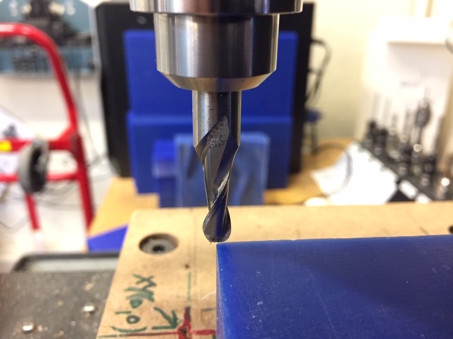
Remove/add tool by gently -
gently pushing the black handle (pictured) from right to left, while holding the tool loosely with the other
hand. It will fall out if you don't.
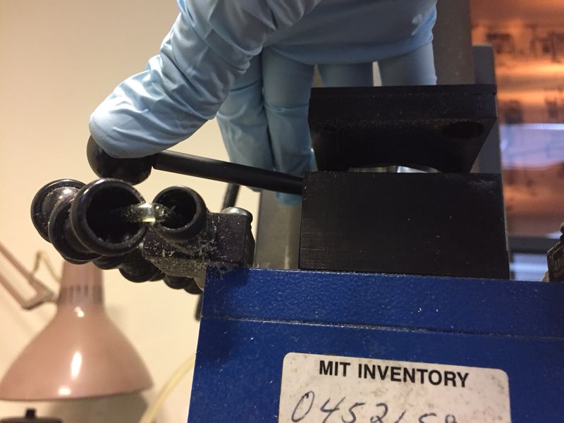
The black handle in the above photo has been snapped off before, when it was pushed too hard.
Please be careful with it - replacements might be very
difficult to get, at this point.
When you unlock the tool with that handle, sometimes the tool sticks - NEVER, never pull on it with your
bare hand to try to remove it - if your hand slips, the flute will cut you pretty badly.
With the handle to the left as in the photo, if the tool doesn't come out easily, and pulling carefully while gripping only the
ring at the top of the tool holder doesn't work,
get help from supervising shop staff.
Wrap a rag around the end mill in any case, to protect your hand, regardless.
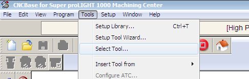
To use a new tool:
Select (not insert) the correct tool from the list
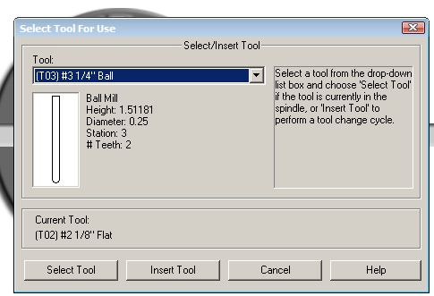
You must make sure the tool number in Mastercam matches the tool number in the controller software (in addition to the actual size/length
of the tool!)
Jog the tool carefully to your X/Y zero at (above) corner of block (yes, eyeball it- edgefinders are not really necessary here)
Set X/Y zero (corner of wax) using "set position"
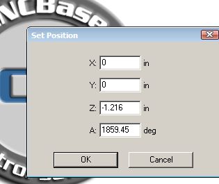
Make sure X/Y/Z zero and orientation of part in real life on machine match your drawing! On this machine, X is the long side.
The tool library should have accurate Z (tool tip) offsets attached to them - but you should always check these before running a job.
Being able to manually set Z is very helpful for anyone operating one of these machines.
Please always set these jobs up with Z at the BOTTOM of the material (top of the MDF spoil board). Although we zero off the tops of the copper
boards on the Modelas, otherwise it's much safer if we're consistent across the rest of the CNC machinery in the shops. So we must default to this
zeroing Z at the bottom of the material.
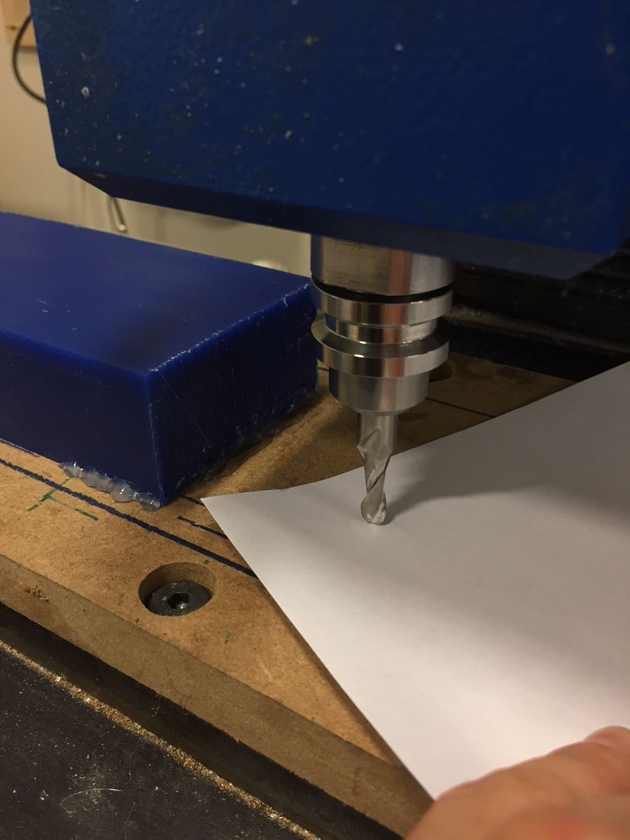
There's a quick and dirty way to set Z zero- it isn't perfect, but neither are MDF spoilboards. This can get you within
3-5 thousandths of an inch from 0.
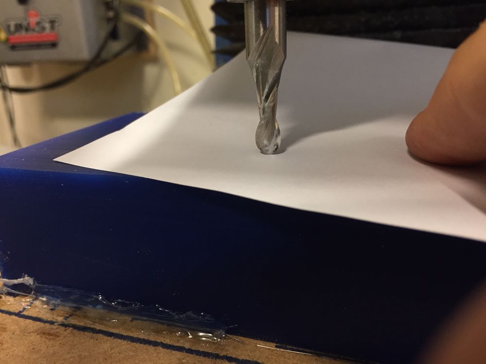
A sheet of 20# printing paper is .003" thick. If you carefully jog the tool in Z, with tiny incremental
movements, while shifting the paper to feel for a little friction, you can safely move the tool about .003" from the spoil board.
You need to pick a spot on the spoil board that is in good flat condition for this to work (the spoil board has to be clean/flat in general
for you to be able to fix material to it, also).
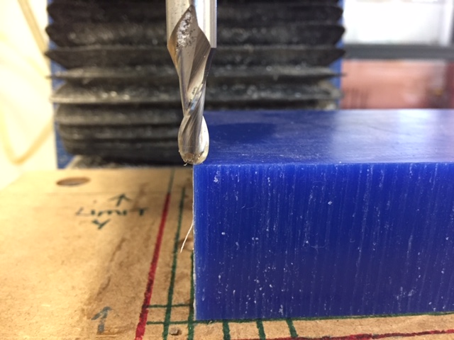
If you touch the tool to the top of the wax, it's possible to set Z here to 1.5" (assuming that is the thickness of the wax). This is not safe unless you
double-check to confirm that thickness and remember to accurately adjust Z zero.
Remember, just like on the Modelas - this only really works if the spoilboard is actually flat, and your material is able to sit flat on
top of it (stays in plane with the cutter's X/Y movements). Checking the machine table and your material carefully as you set up will be
necessary to minimize any risk of issues related to things being out of plane.
Notice the glue bead on the above photo - it's jammed well into that corner, with lots of surface contact on the wax and the MDF. That's what you
need to do to secure these to the table, but also keep it possible to remove them after without destroying the spoilboard.
This is something that doesn't really happen on the Modelas, but which you need to be careful of in general - you don't want to hit the machine's travel
limits in X, Y, or Z. It will error out and force a re-home/restart if it happens. It's easy to jog right into them if you aren't being careful.
There are lines drawn on the Intelitek spoil board to show you where the boundaries are that you need to stay inside of in X/Y.
When the machine is homed
at the beginning of all work, check out its Z position by looking at the flexible accordion-ish black plastic cover- that's its Z height limit.
If you're prompted to re-home the machine any time during setup, you'll have to check/reset X,Y, and Z zero again. So be careful not to jog the tool too
far in any direction - if you hit its limits, you'll get a warning from the computer to back away from
them, and then you'll need to re-home. This happens on the Shopbot, also.
Any time there's risk of a CNC machine having lost its position, it should force you to re-home it, so it can confirm where it actually is
within the area it's able to move around in.
When they're first turned on, they need to do this - the laser cutters and Modelas do it automatically as they initialize; the other CNC
machines make the operators home them as a first step.
Always have a second set of eyes check your files before attempting to run them, even if you are approved as shop staff to operate these
machines. If you are not, you must have shop staff check your files before any gcode is generated.
When your file is approved, and gcode is ready, open it in the Intelitek software and press green play button to run
Blue = pause, red = stop
You'll need to do the process for each tool needed.
Clean up machine - vacuum up all your shavings, including what falls off the table!
Shut down controller, press red Stop button to deactivate power
 RESERVATIONS
 HOURS
HOURS TUTORIALS