Understanding the tools (end mills & other router bits, tool holders)
The below image shows a few different types of tools that cut while spinning. The upper row tools are all solid carbide general purpose
end mills. The bottom row has 2 carbide-tipped router bits, and last, a simple drill bit. These 3 types of cutting tools
are very common, but they need to be handled differently.
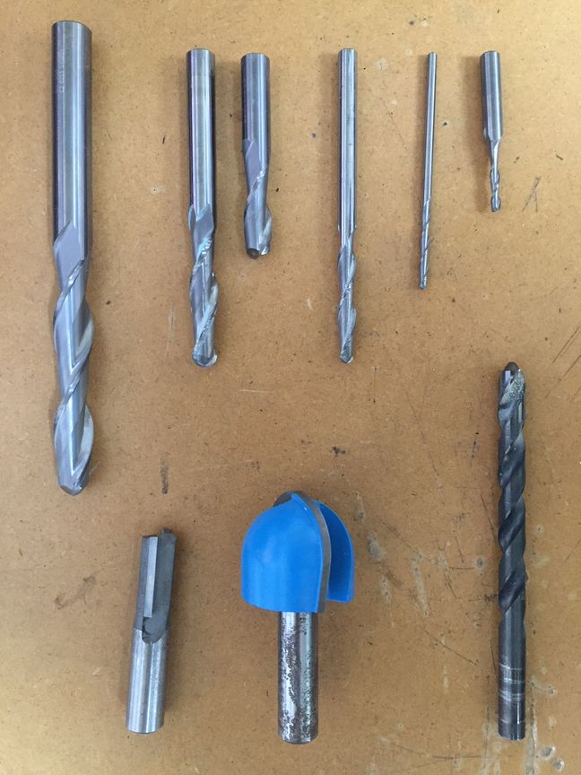
Look closely at the difference in the shapes of the end mills vs. the drill bit. There are differences between the solid
carbide and carbide-tipped tools, as well - there are many very different types of router bits that wouldn't fit into this
page.
This tutorial will be focusing just on the basics of 3 axis machine setup for milling materials like foam,
plywood, and MDF, and will only refer to on work done with solid carbide end mills. Just keep in mind that the tools above are
handled very differently.
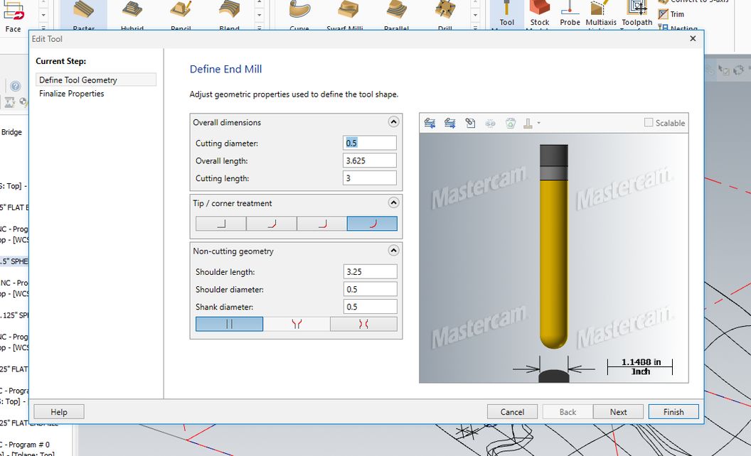
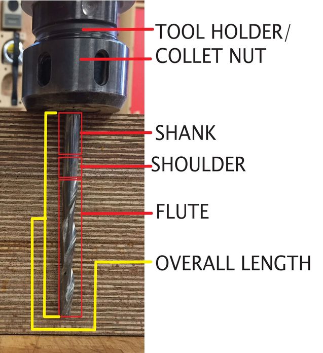
It's extremely important to recognize the flute, shoulder, and overall length of the end mills we'll be using.
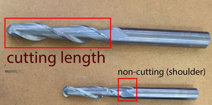
The flute, or sharp cutting edge, does
not extend all the way up to the edge of the recessed spiral on the tool.
In the
photo below, the cutting edge of the end mill ends almost 1/3" of the length down from the collet holder. The
cutting edge/flute ends at the tool's "shoulder", which is just the transition between cutting edge and the fully solid cylindrical
upper part of the tool, called the 'shank'. The shoulder cannot cut.
The shank is the solid part that a collet must clamp onto,
to hold the tool securely in the spindle. The tools must be inserted fully into the holders for maximum surface contact between
the shank and the collet, so that it will not move at all during use. So a tool's total length is usually shortened quite a bit once it's
inserted into a tool holder.
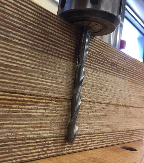
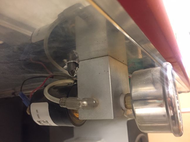
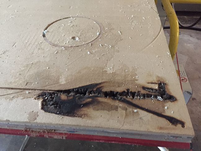
The above image shows a long half-inch diameter tool, installed in one of the Onsrud tool holders, up against a block of
material that was used for a project. The tool clearly is not long enough to reach all the way through with the overall
tool length, never mind just the tool's flute length.
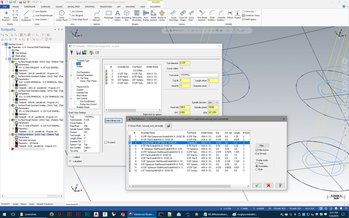
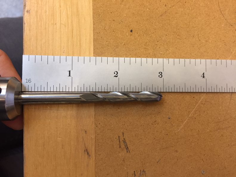 Anyone setting up router files absolutely must always know exact tool measurements - flute length, shoulder length, and overall length.
These
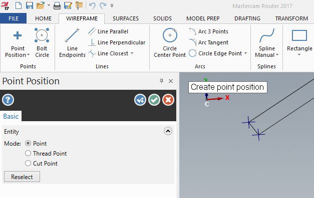
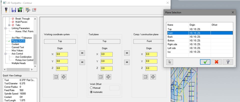
are measured from the tip of the tool up. There is an illustrated tab in Mastercam toolpath settings where these lengths are shown (in
the case of a preset tool library like the Onsrud) or in the case of Shopbot or Prototrak setup, the lengths for each tool must be measured every single time
one is installed, because every time the overall tool length is going to be at least slightly different.
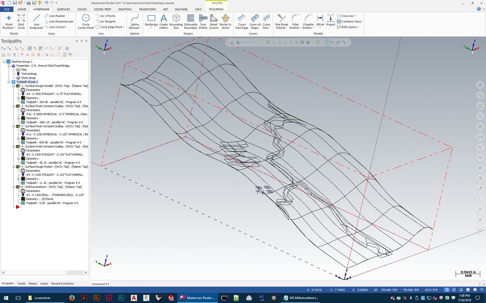
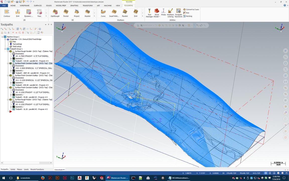
Now you can start setting up toolpaths. There are a few basic concepts that are important when envisioning how to start:
- Toolpaths are driven/defined by either surfaces or curves.
- There is often a lot of excess material that needs to be removed to get down to finish surfaces, in which case we need to do roughing tool paths
to remove that excess before finish toolpaths can be run.
The process will need to be broken
down into several steps for most jobs- you'll need to be able to plan out the best way to approach the cutting operations for the
best/fastest results.
- We tend to envision these tools cutting at the tips, but they really want to cut on their sides. The flute lengths (cutting edges) of these can be long, and the tools
are happy cutting wide ribbons of material from their sides - but those ribbons, or whatever shavings are being cut cannot be too thick or the tool will be overloaded.
The thickness of those shavings, or chips, is found on a chipload calculator - spindle speed and feed rate are determined using this calculator based on material type, tool
diameter, and tool type (solid carbide end mill vs others).
The flute is the only part of the tool/tool holder that can ever be allowed to come into
contact with the material. The shoulder/shank/holder can never touch material - and the tool can not be allowed to cut down into the machine's spoil board
(below Z zero).
- The tool's movements must be set up manually with very strict control - and any excess material left outside the edges of toolpaths also need to
be taken into account. Potential collisions with the non-flute parts of the tool and its holder are always dangerous and cannot be overlooked in setup.
Collisions and too-deep cuts are major fire risks, so staying hyper-aware of where the tool will move at every step in the job is extremely important.
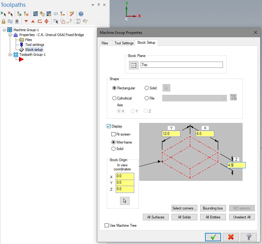
The first step in controlling this is making sure the tool and material dimensions are defined 100% accurately in Mastercam.
Roughing Toolpaths
With any material thicker than a sheet of plywood/MDF and surfaces to produce with single/double curvature, there will usually be
a lot of material that needs to be 'roughed' away
before you are able to approach the finish surfaces of the object with the tools. We usually cannot cut immediately down to finish surfaces.
Roughing is going to be the first step for most
work done on the routers (one exception would be the most simple jobs - 2D curves cut into a single thin sheet of material with a
compression endmill, which needs no roughing).
If the roughing part of the process is forgotten or mishandled, fire and broken tools are almost inevitable. Roughing toolpaths are mandatory, and good ones
will be efficient, also minimizing stress on the tool.
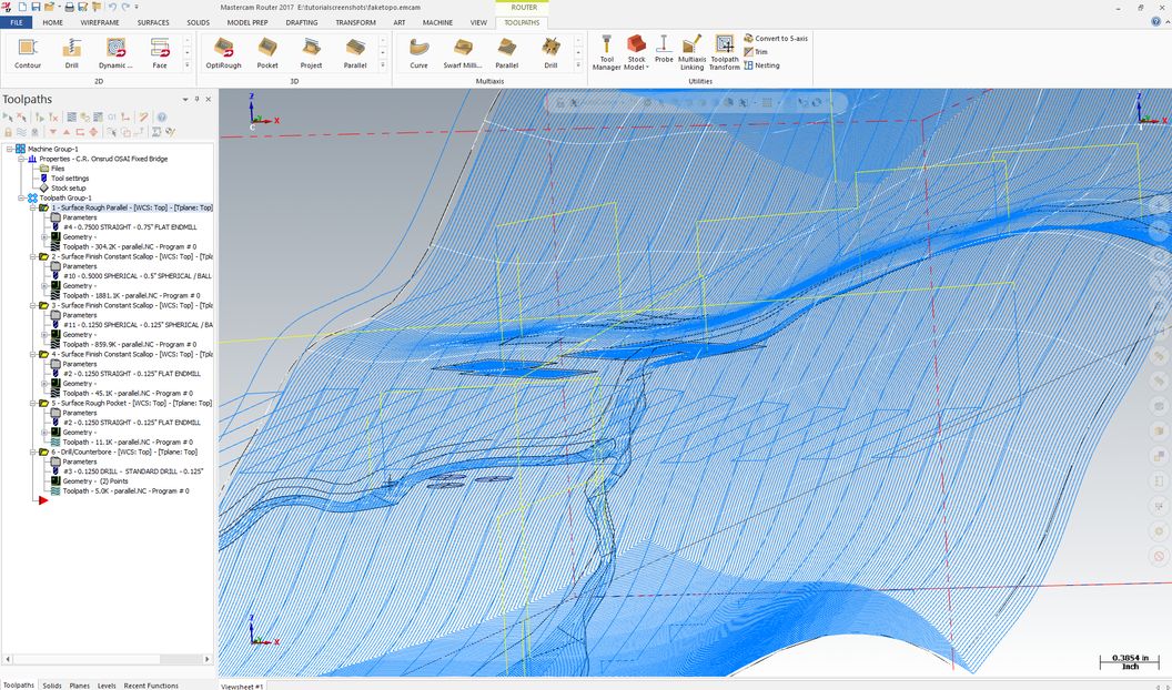
There will often be more than one option for particular details - Mastercam has lots of options- but some will be faster than others, and some will produce nicer
results. One thing to keep in mind regardless, though, is that you should never expect to be able to cut any 3 axis job in one or two
blanketing toolpaths. We need to break these objects down into multiple parts with multiple treatments for faster and better quailty results. Some of the
toolpath pattern choices are better for safety reasons, speed reasons, and some finish toolpath options also better because their patterns are better suited to
the surface finish you are looking for.
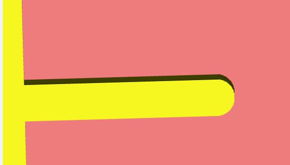
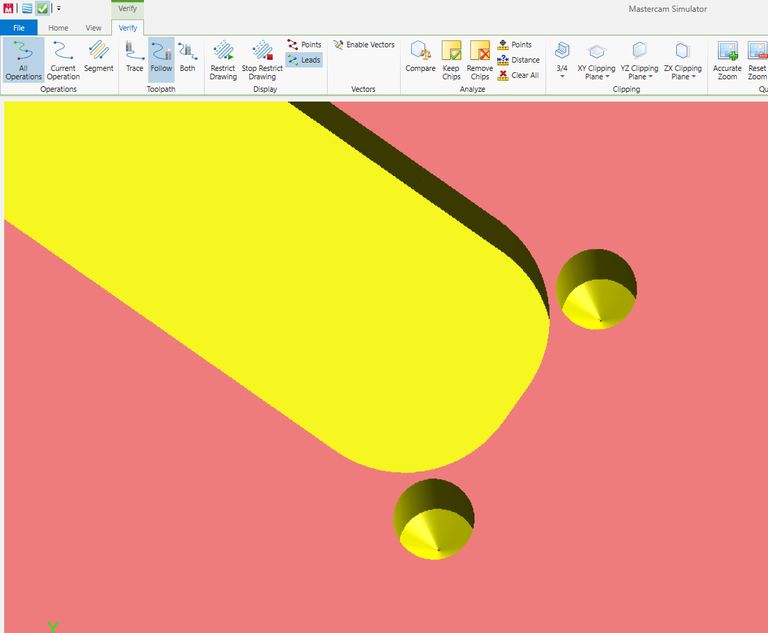
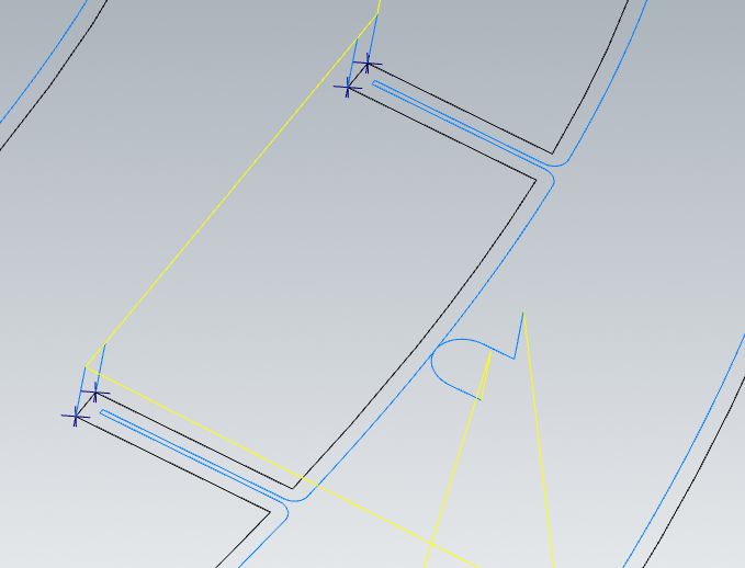
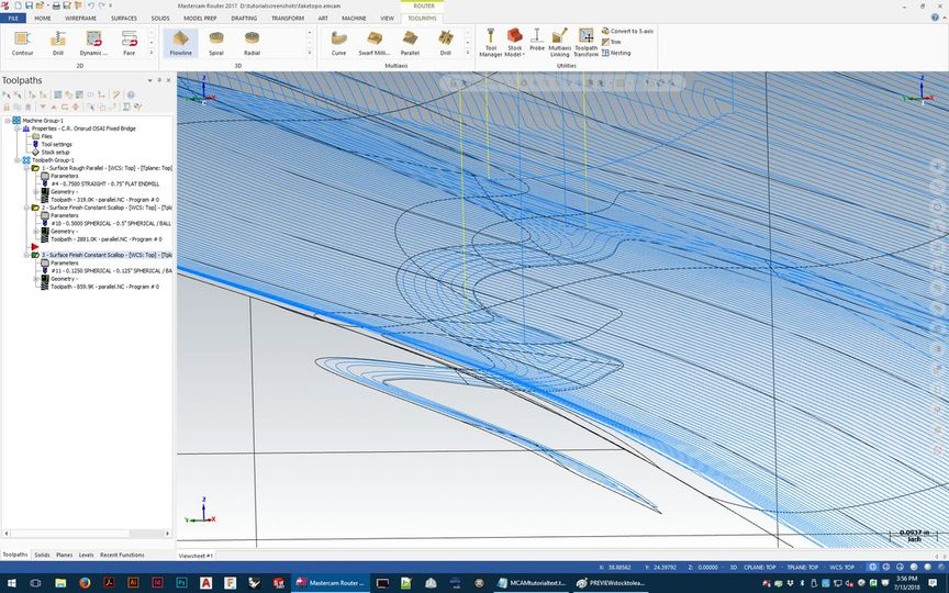
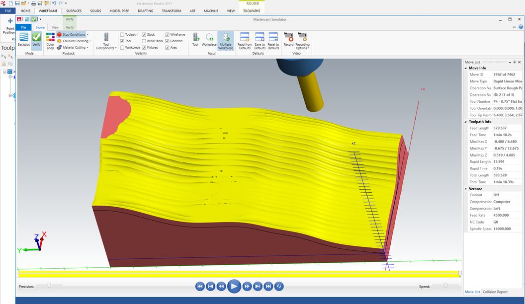
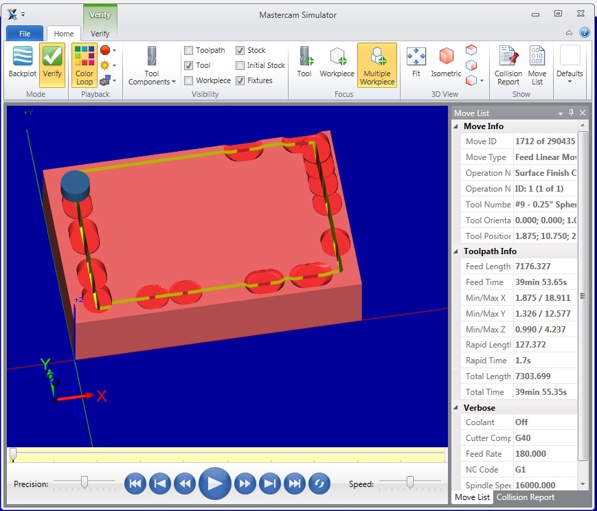
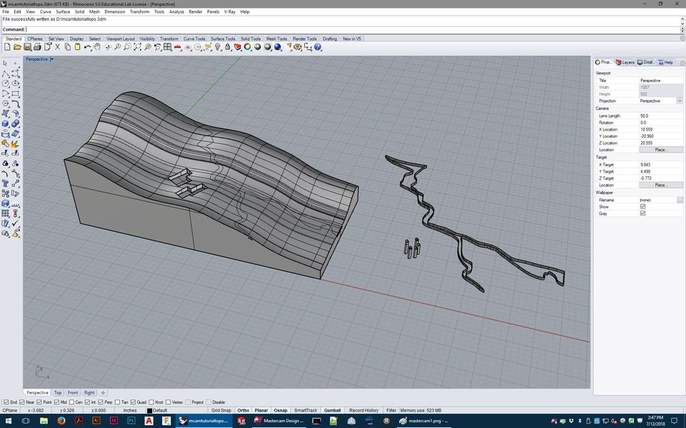
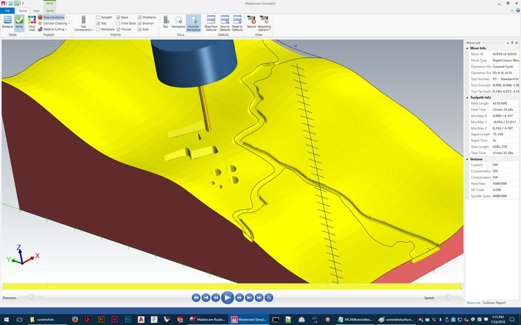
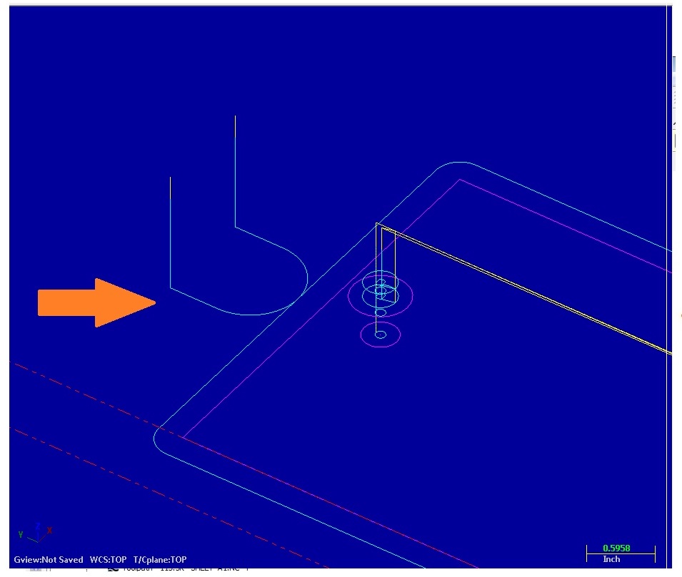
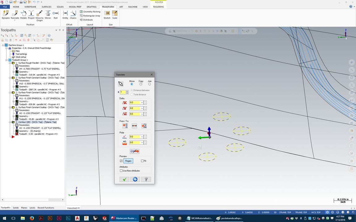
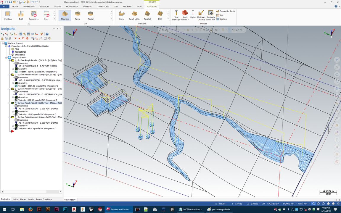
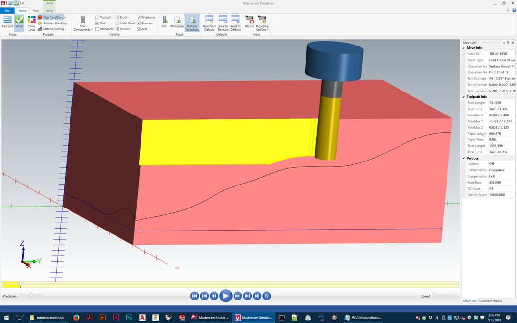
The image below shows a preview of a roughing tool path in progress (defined by a topography-like surface).
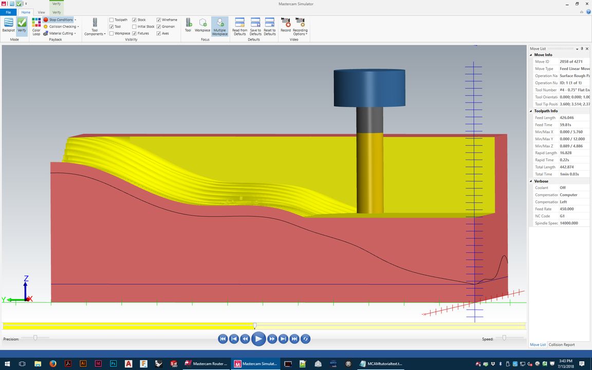
See how the yellow flute (cutting length) of the tool is only able to reach partway into the material to the curve (where the finish surface is)?
The roughing tool paths need to do 2 things - cut away as much material as safely possible without wasting time or stressing the tool,
and also without plunging too deep- only the flute can ever come into contact with the material. If it goes deeper, melting/burning
happens immediately- and the end mill can just snap like a twig if it's overstressed.
That tool is also too short to reach the bottom of the surface if we
don't clear the top away - the blue tool holder will crash into any leftover material on the back side if it isn't all cut away.
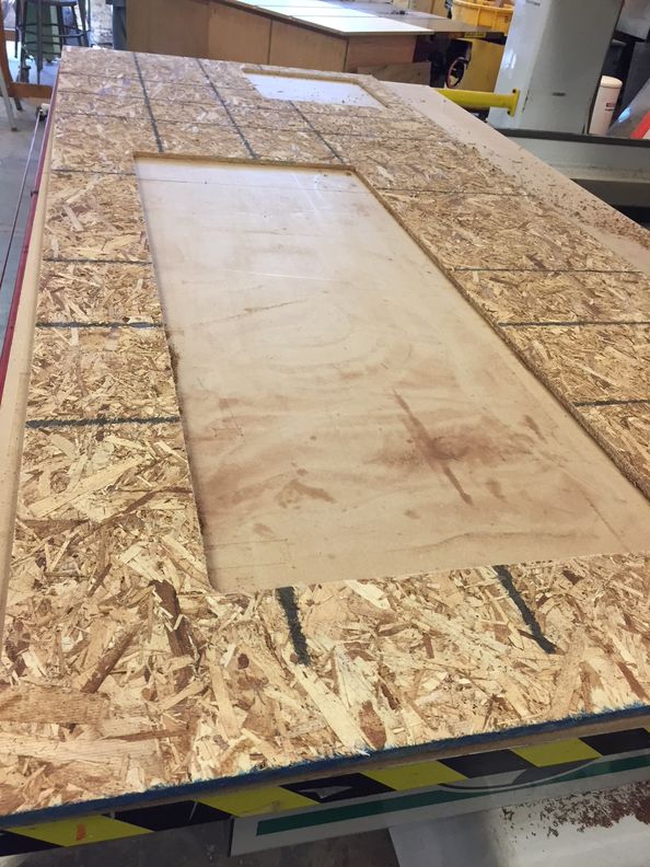
This is one reason why the size of your material and correct dimension
input into the software is so important - it can't warn us that we're going to crash if we don't tell it the truth about the block of material on the machine.
You'll prevent all this by carefully setting the details of your roughing toolpath.
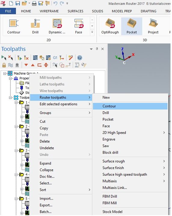
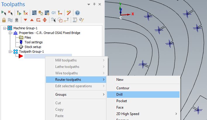
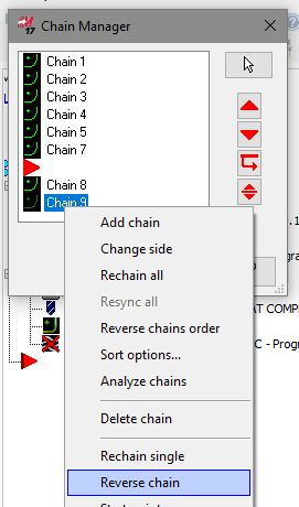
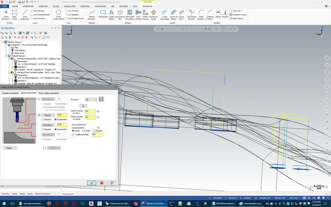
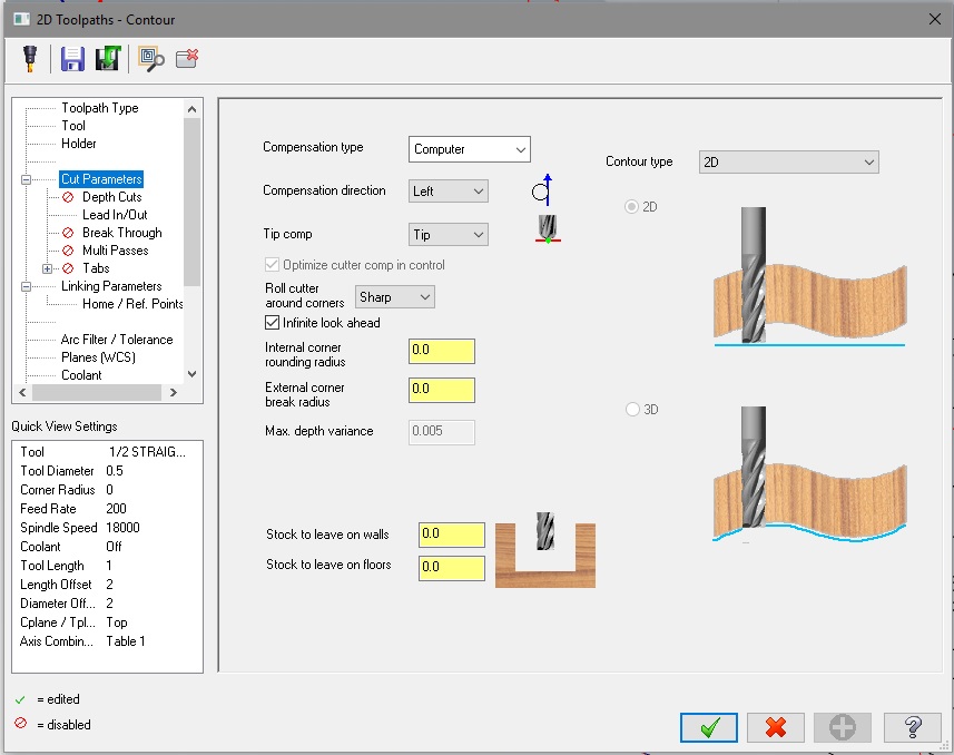
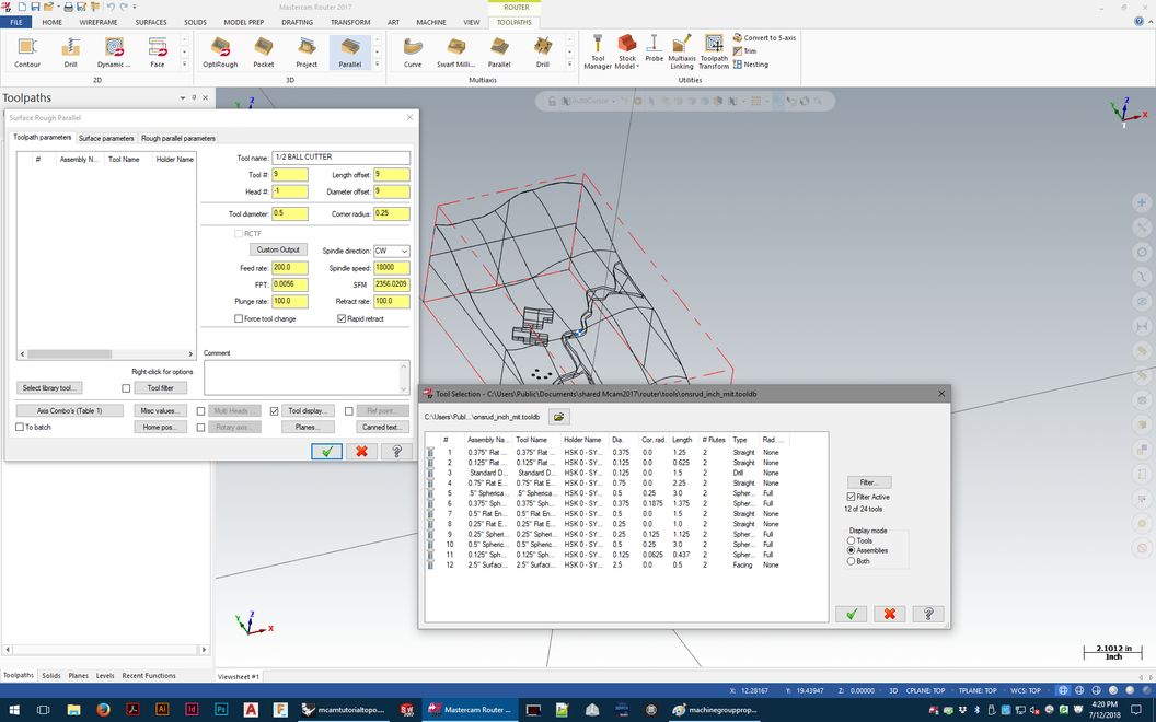
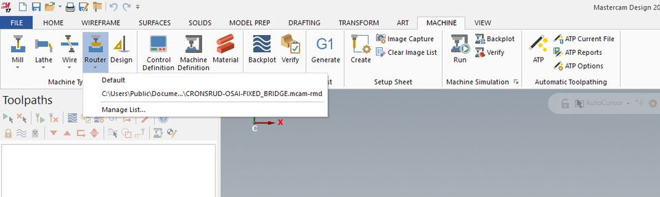
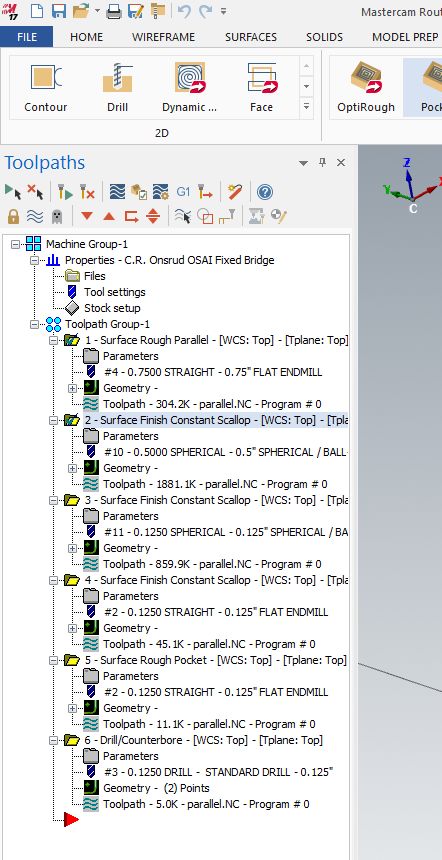
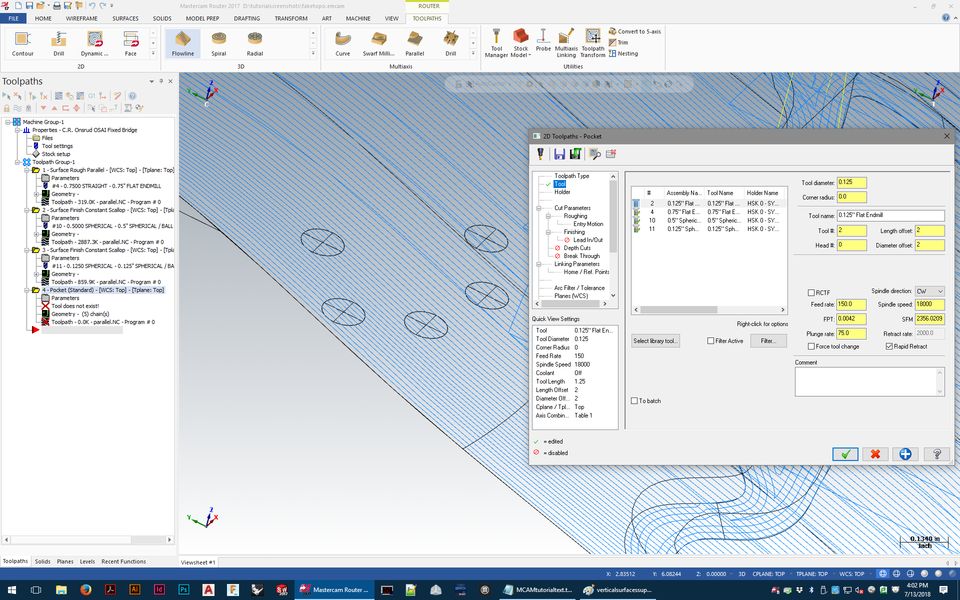
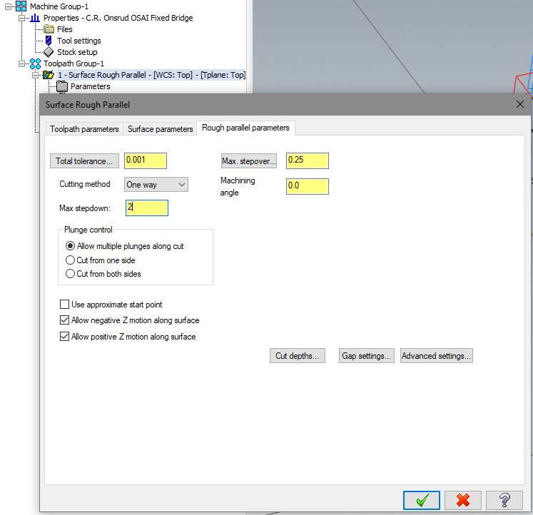
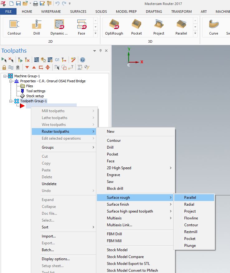
We almost always use "surface rough parallel" to rough out excess material.
Right-click on 'toolpath group 1', and go to - router toolpaths - surface rough - parallel
Need screenshots here - specific toolpath settings
Pick tool from library - generic if Shopbot or Prototrak - Onsrud and Intelitek do have real tool libraries. Make sure you're using these!
Feeds and speeds are set (in a general sense) for the preset tool libraries - Shopbot/Prototrak must be typed in manually. Chipload calculator must be used!
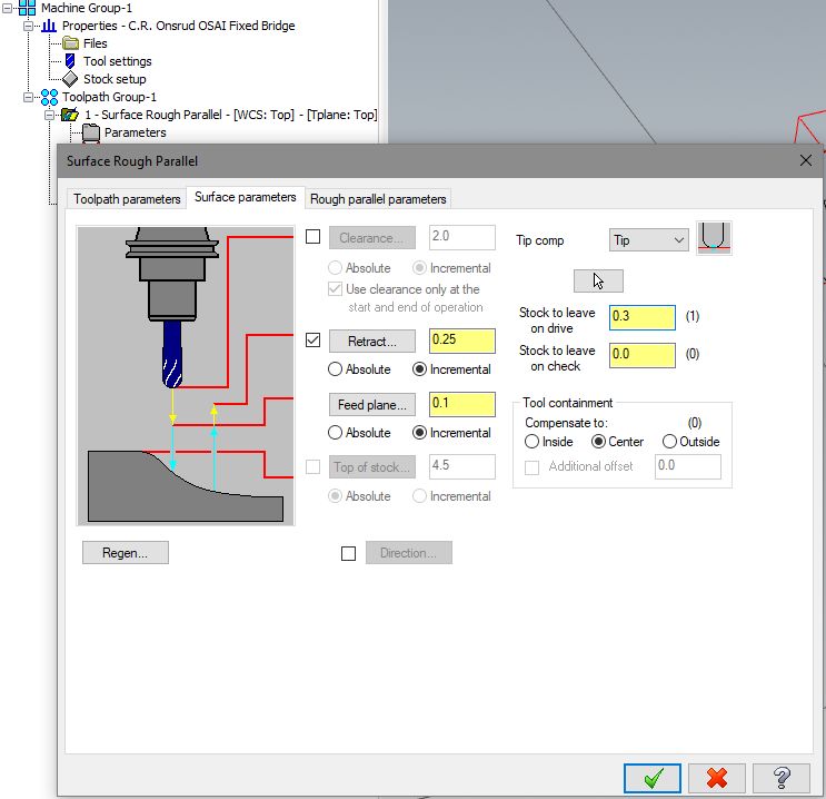
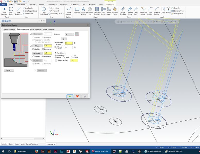
Linking parameters - retract and move heights must all be set to retract the tool to a safe distance so it will never crash into material while moving over it.
In Linking parameters, we leave a small amount of material on the drive surfaces. The toolpaths leave 'mill marks' in material,
just like any other cutting machine - if you want to remove the mill marks from roughing, you need to leave a skin of material
on the 'drive surface(s)'
Toolpath (rough parallel in this case) parameters - step down step over, zigzag, move up/down in z multiple times... must explain step down/over -
add wax cutting info? Tool wants to cut on the side, but if we are roughing out a pocket with non-flat surface at the bottom, cutting at the tip of the
tool for parts of the toolpath is inevitable. If there are no outer walls to keep, you can set the toolpath up to start off the edge and cut mostly
on the side.
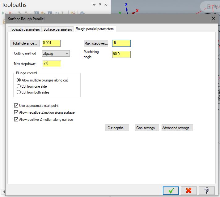
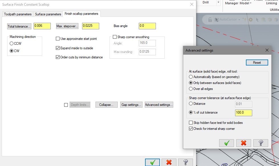
Tolerance settings? adjust cut depth? - less important
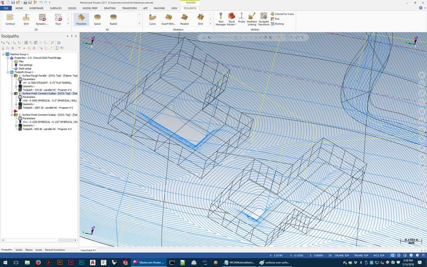
A roughing toolpath will almost always leave large chunks of extra material in places - you must preview the job and carefully note where they are.
Those must also be cut away carefully. Sometimes a finish toolpath can do that - but if a finish tool has a shorter flute length and it would pass by
the upper parts of that leftover material, it will collide and cause burning, melting, or breaking. Methods for removing the extra material will vary
depending on the specific geometry.
random notes -
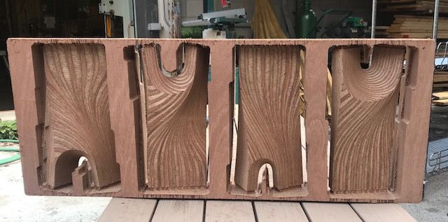
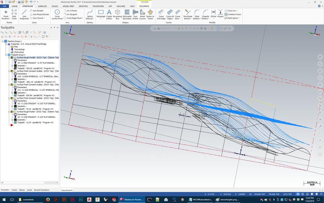
With really thick material, it's necessary to rough in steps down ('stepdown' setting in the roughing toolpath) to approach the
finish surfaces, because the tools' flute lengths just aren't long enough to cut that deep in one pass - even in relatively soft
foam this is not possible.
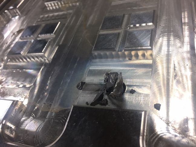
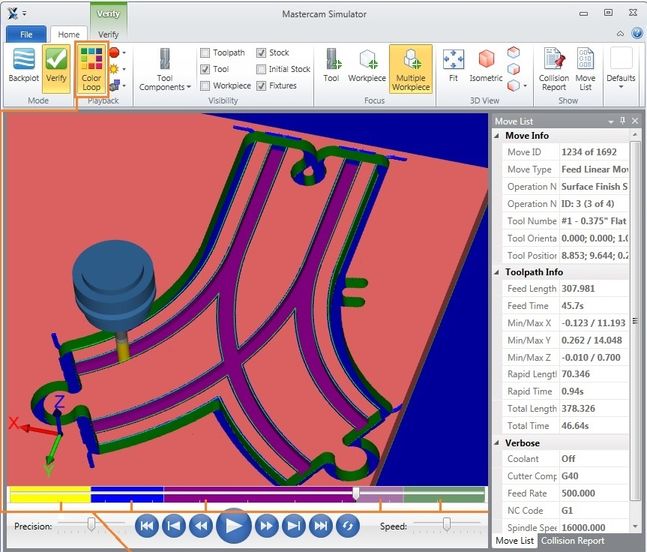
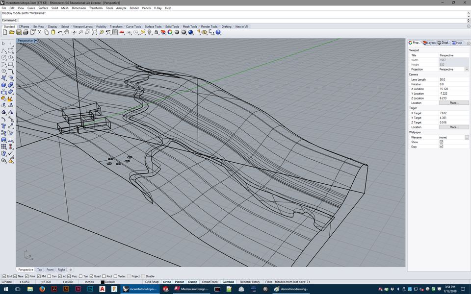
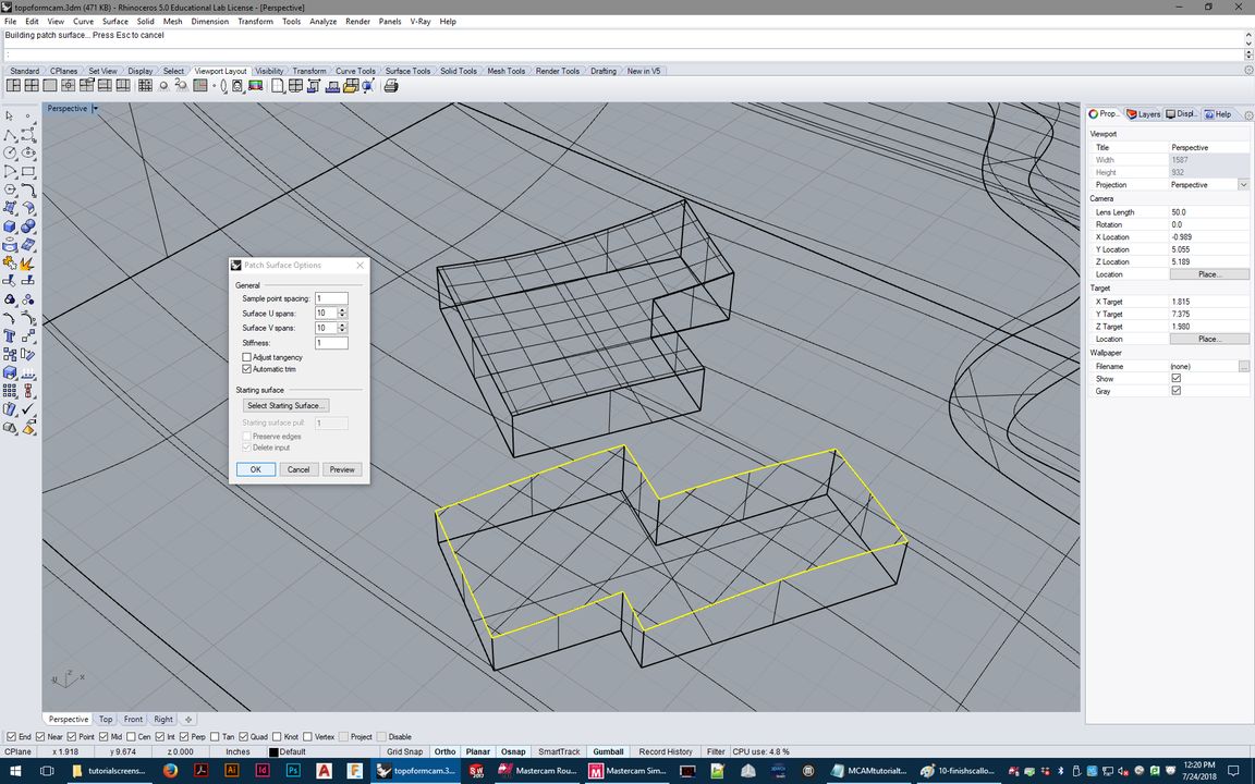
As you can see in the images, if you were to try to plunge immediately down close to the finish surface, the shoulder/shank/collet
of the tool would crash into the material. Foam will crush/tear when this happens- but because the spindle will be spinning at
several thousand rpm as it happens, the friction will also cause melting - this cannot be allowed to happen. Melted foam will get
in the way of the tool cutting properly, and also releases dangerous (usually styrene) fumes.
But if the material is thinner, can you safely skip this? The answer depends on some details.
The roughing is going to be done with tools with wide diameters - normally .75 if on the Onsrud, or .5 if on the shopbot (.5" is
the largest diameter tool the Shopbot can hold). There's no reason to rough with thinner tools - it's efficient to rough away
material as quickly as possible (with proper feeds/speeds set using the chip load calculator).
If you have thinner material, like a single sheet of 2" foam, and you want to skip straight to finishing, and all the tools you
want to use have flute lengths that can safely reach the finish surfaces without any collisions, then in such soft material, it
would be safe to do.
If you're using hard material - plywood, MDF, solid wood, wax, plastic, etc., then you probably will not be able to go straight to
finish toolpaths with thin tools.
The problem is that attempting to plunge into solid material and push the tool sideways as it attempts to cut its full diameter in
hard material is bad for the tool - in a situation where you're trying to skip roughing, if thinner end mills are plunging deep,
they're almost guaranteed to break immediately.
If you're skipping roughing, you're more likely to be attempting to use tools needed for finish details, which are more likely to be
narrower in diameter.
When plunging deep into material (like in a deep pocket) is unavoidable, the toolpath, if set up well, should start by carefully
opening up a space deep into the pocket first, just wide enough for the tool to have some breathing room around it (while not
cutting deeper than the flute length can cut), and then spends the rest of its time cutting mostly or entirely just along the side
of the tool, rather than dragging around at the tip.
 RESERVATIONS
 HOURS
HOURS TUTORIALS