Dropbox - 4.140 template files for the group test- you have the option of merging your own geometry into the Mcam file and starting
toolpath setup yourself. Shop staff will check/edit the file before attempting to cut.
OSB (and other plywood) press fit cutting
This page concerns plywood press fit projects - this information is relevant to projects done in 4.140 and 4.500.
Like the laser cutting assignment in 4.140 and 4.500, this is for press fitting. Unlike cardboard press fitting, plywood/OSB is dense and will not
compress if the notch fit is off.
Notch fit testing is 4.140 group work for the week - you must head to N51-160 ASAP this week to get that done - every batch of OSB even from
the same supplier will have a slightly different thickness. You will need to know what notch width in a CAD drawing will cut out to fit
well in real life. Measuring the material with calipers will not usually give you exactly the same result. .01 or .02 inches of difference
between test widths will give you noticeable differences in notch fit quality.
Regardless of which class the work is done for, the best notch fit width must be tested IRL (you cannot trust the 'named' thickness) and everyone in the class
needs to size their notches accordingly. Sheet material will vary slightly in thickness from batch to batch - they will never be exactly the same.
In your preferred CAD software, draw the border of your assigned material (one sheet, 48x96 inches) - and fit your parts inside it.
Please note -the machine wil NOT be cutting over the center of the lines. The cutting tools have diameters, and CAM software
will offset the tool to the outside of the line (unless we tell it otherwise). So draw your objects without worrying about offsetting lines for
kerfs. The tool width does still need to be taken into consideration in that you can't make details that are too small.
Material properties themselves are also something that you need to consider when designing part sizes. Half-inch thick material is very weak in narrower strips
and will not withstand much stress.
We can cut strips of OSB for 4.140 to try breaking manually so you can get a feel for it before designing for something made with it. This is something you
should try ASAP along with the notch width testing.
4.140 is working with 4'x8' sheets of "half inch" OSB this week. Each of you has one sheet to work with, so please plan for that.
They will be waiting for you in N51-160, where the Onsrud lives. This is the large router we need to use to cut this material.
This OSB is called (nominal) half inch, but is going to be a little thinner than that. There are always slight differences in
thickness of wood product sheet material from batch to batch - MDF being the most accurate and most consistent (it is the most homogenous among them, being made basically
from dust and glue - and so easier to control in manufacturing).
This is a good thing to learn immediately about sheet material- the dimensions are not usually exactly what they're said to
be, especially with cheaper spongier plywoods. In terms of area, some 48x96 sheets will actually
be 48x96 inches. Some will be slightly larger. In terms of thickness, a sheet of cabinet-grade veneered plywood that is called 3/4" thick is usually
to be at least 1/32" thinner than that. The OSB we get always varies a little - its faces are not flat 2D surfaces to begin with.
3/4" MDF is one
type of sheet material that is usually slightly bigger than 48x96, but actually a pretty reliably accurate 3/4" thickness.
In general, expect to have to check these things repeatedly when building with wood product sheet material until you become very familiar with them. Planning cut lists for parts, whether
press-fit or other construction, requires accurate thickness measurements for accurate final product dimensions.
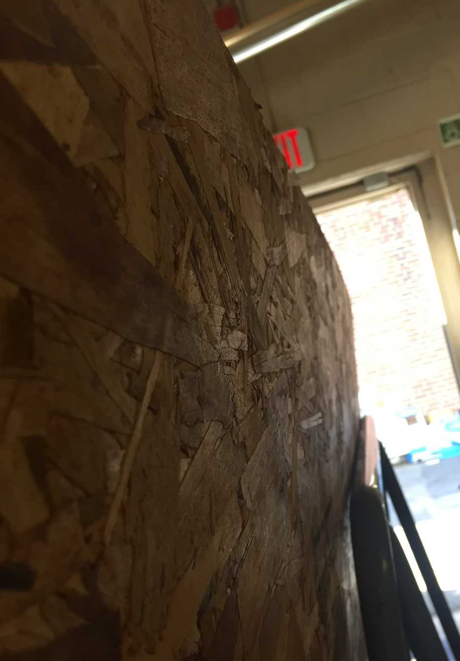
One side of this OSB is super bumpy. It's smoother on the other side, but not smooth - clearly shredded scraps in an
"orientation". When you look closely, even the smoother side is not flat at all. You'll see a side effect of that when you check
out your onion skin.
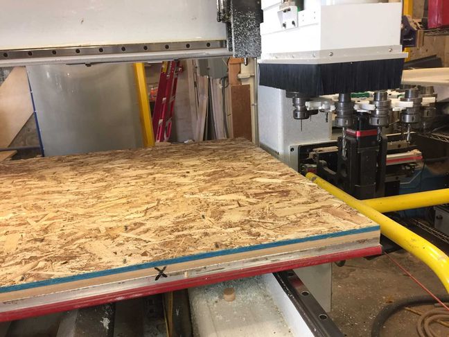
We put the smooth side down on the Onsrud table for better vacuum. This material is cheap and bumpy (and often warped) enough that we also have
needed to put screws in safe locations to hold it down, despite the high quality vacuum table. That means we have to be very careful on every job
to make sure we do not put the screws anywhere near the path of the cutting tools. Everyone involved in these cut jobs needs to be vigilant about this detail.
We also need to try to leave a margin around the edge not just for screws that may need to go there, but also because the vacuum is weakest at the edges.
Please try whenever possible to not extend your parts all the way to the edges of the 48x96 rectangle.
For the group projects, you should cut out a test for press fitting (files already available in the Dropbox),
but if you didn't get one in 3-412, also ask for a thin strip of this material
to be cut on the table saw so you can feel for yourself how it handles (or doesn't handle) tension. We should be able
to spare several inches off the ends of a sheet so you can try bending and breaking this stuff - you should experience it before
you attempt to start designing objects that will not survive in this material.
Limit yourself to one sheet for this assignment, please. We have
a lot of students to get through by the deadline - final project work can be handled afterward.
Here
is a Youtube video of someone testing various types of sheet material, including OSB and particle board.
It's important in any design of physical objects to really understand the benefits and limitations of the materials
you're choosing (or are given, in this case).
I can offer a Zoom session to go over Mastercam setup basics when I'm off campus; each student in our section must submit a drawing (can be a quick
concept sketch) of their idea for this week's assignment ASAP - preferably Thursday by end of day.
The Onsrud is fast, but it's just
one machine for 1.5 sections, so we need to not delay on getting started. Making time on Thursday/Friday to do group testing for notch width (and also snapping a
thin strip to get a feel for the material's behavior) is what everyone should do first, before making detailed design decisions.
How is material held down on the Onsrud?
Unlike the laser cutters, which don't put any stress on the material, routers are a very different story. Material must be held down very securely.
Some machines, like the one we'll be using, have a vacuum table to hold things in place during cutting. Its MDF spoilboard (a 'sacrificial' layer like the copper
boards we tape down carefully on the Modelas) is machined very, very flat/parallel
to the X/Y cutting plane, and long story short -
the vacuum sucks sheet material down onto it, instead of needing screws or glue or other fasteners. A good vacuum table
is an investment in space, time, electricity, and money, and does have its own limitations, but can be extremely convenient for a
router owner. A vacuum table is pretty great for a lot of reasons,
but not undefeatable. Material needs to lay very flat on the table for the suction to work - larger areas are held
down better.
Some years, our OSB is flat enough to stay down with just the vacuum. Sometimes, though, it's so warped (again, this material is not made
for furniture making, so it's not generally expected to be great quality) that it needs a few screws added in safe locations to hold it flat.
Also, small pieces just don't have enough area to be
held down at all, once they're cut loose. Any part, even large, heavy pieces can get grabbed and thrown off the machine by
the end mill if they are not held down securely enough, and if the tool is given a chance to bite into it enough to do that.
We arrange parts so smaller ones are not at edges, screw to the vacuum table if necessary, and for small objects can also make shallower cuts.
These machines get very dangerous very fast - so toolpath setup has to be done carefully and intentionally by sufficiently trained and experienced
operators to minimize risk of any moving parts or collisions with loose waste or screws, as well as the very significant risk of fire.
Onion Skin hold-down method:
One nice, and commonly used method to compensate for the weak points of a vacuum table, lowering risk of thrown pieces and/or fire,
is to cut almost all the way to Z zero, but not quite. To a point, this very thin material left on the table will help keep parts from
shifting and being damaged or destroyed.
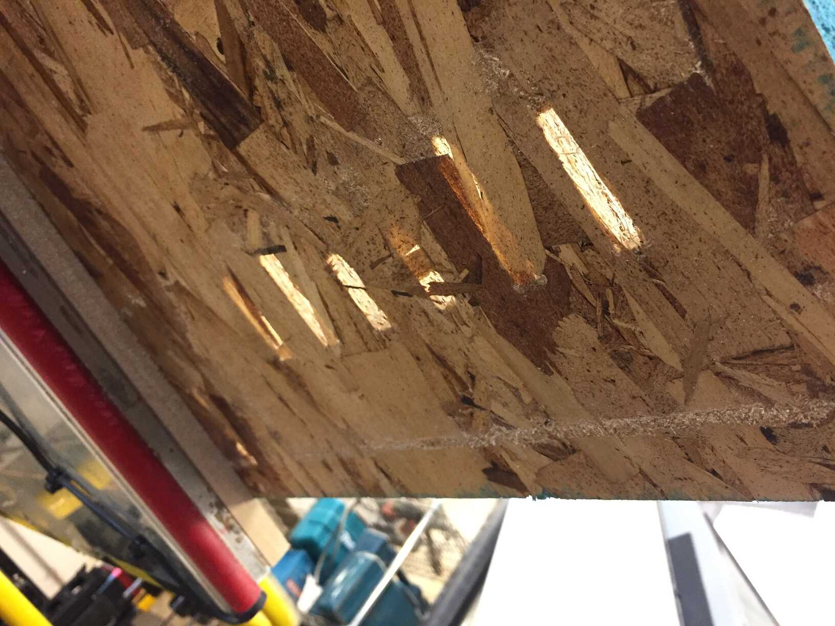
This is called an 'onion skin' - a super-thin leftover layer of material that remains against the vacuum table.
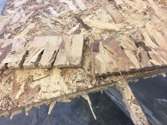
My first test had a .03" skin - it was too thick to easily break parts off afterwards. Second test was .008" - the result in this
photo. You can see that the endmill cut all the way through the sheet in some places with this setting. There needs to be enough material left to
securely hold them down during cutting, but not so much that they're difficult to remove after. After my tests, Chris and students found that it was still
not sufficient - so the current thickness left over in the test file is .015".
You will need to limit small parts to 6"x12" or larger.
If you desperately need smaller parts, we need to make that skin thicker, at least .03"
with this not-flat OSB surface, to ensure that they don't get ripped loose and destroyed by the end mill - or compressed,
starting a fire.
And then with that thicker skin you just have to do a little more hand work to separate them afterwards- no machines. Small parts will get ripped
out of your hands and your hands will go into the sander/router/saw blade.
An extra thick onion skin for smaller parts requires a separate toolpath (easy but
important to set up correctly).
File type? Tetris? Notch fit?
Just like in laser cutter week, this is a press-fit project. Unlike the cardboard you used, plywood is not
forgiving when notches are off-sized.
I drew a quick set of notches of a variety of widths, based on the width of the OSB we have (never trust the named thickness of plywood
or masonite - they're usually smaller).
We need a 2D curve drawing just like we'd set up on the laser cutters. A dxf, dwg, 3dm are fine.
You'll want to be able to control notch width in your own part file parametrically so you can adjust them based on the
results of your notch fit testing (like the test I did, but hopefully progressed a hair further).
Please carefully arrange your parts in a 4x8 (48x96 inch) rectangle.
The tool we're using is .25" in diameter - so there will be a kerf of that width around all the outer edges of all
the parts. Your parts can be close enough that they overlap in spots if necessary.
The vacuum is weaker at the edges of the two halves of the machine table, so avoid putting any small parts near the edges (keep a margin of a couple of inches
all around the 4x8 area in most cases). They're more likely to
vibrate, and tiny parts are more likely to get shredded.
This is "half inch" OSB, but careful checking with calipers around different spots on a couple of sheets showed
a variety of results. So I made notches with a range to test.
The calipers read (in inches)-
.460
.461
.486
.486
.467
.4785
.499
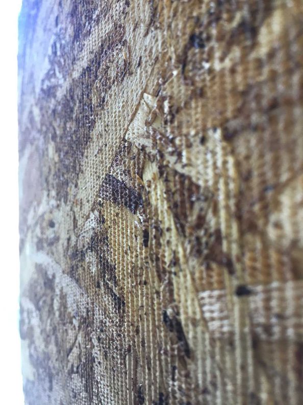
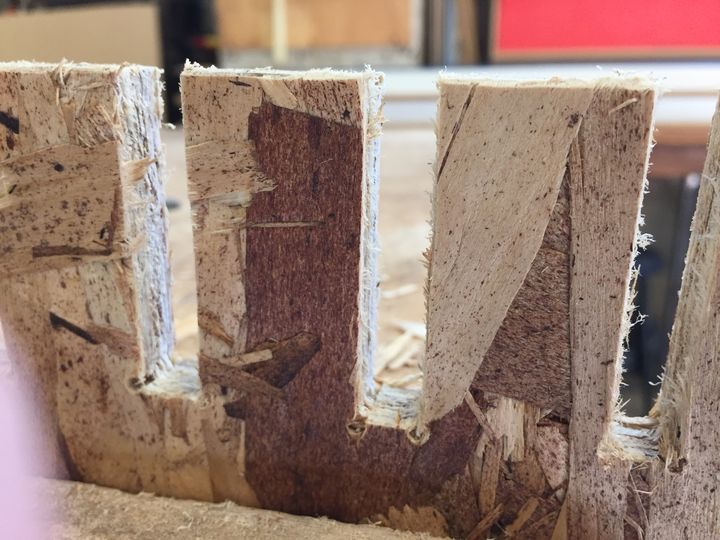
In 2022, after cutting and cleaning up the messy edges with a file, only the .5" notch fit. I took a closer look at it -
you can see in the photos how fuzzy the sides of the cuts are.
We used a completely new end mill (using dull or dirty end mills can produce bad results and be a fire risk) - so
if we wanted to test further we really ought to be able to get these to cut a little cleaner than this.
This is just after separating from the sheet (*make sure you vacuum up all the leftover dust before and during the
moving/removal of parts from these sheets!)-
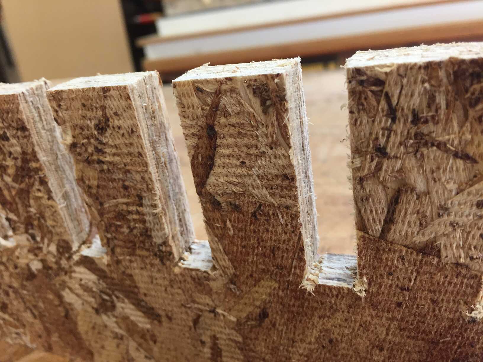
This image is after some gentle file cleaning.
I carefully filed the onion skin shredded edges off with an appropriately sized file (you need to go
in at an angle to get the edges, so the big files don't really fit for those). Then I tried cleaning up a little of that fuzz
- but didn't bother trying to go too far, because it's very easy to ruin joint faces with hand tools like this.
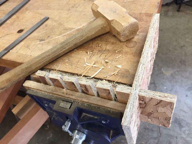
The .5" notches fit well - I did have to gently tap them together with a mallet (if they slide together by hand they're
probably a little too loose!). You may have shorter or longer notches in your parts - remember that there is going
to be some friction here, and that you don't want them to wobble, but you also don't want the notches to force each
other to split apart at all when tapped together. This material will not survive that undamaged.
As far as the fuzz on those interior notch faces go, you really don't want to aim for messy results on a machine that
require a lot of cleaning afterward - your hand tool
skills won't match a machine's accuracy, and you'll just take things out of flat with something like a file or nasty
belt sander.
The fuzz on my test wasn't too bad, but if I'd had another 45 minutes to test, I would have at least tried
to see if I could refine the feeds/speeds a little to get cleaner cuts.
The best thing to do is put the extra work in to cut as clean as reasonably possible, and leave yourself
as little manual work as possible.
You can test slightly wider notches than I did (really didn't expect the .5" to be the one that fit) and also try
taking a closer look at the feeds and speeds with the TAs/staff to see if you can zero in on even cleaner results.
This year (2023) my test cut did NOT fit @ .5" - it was too loose. You will need to do tests yourselves to see which notch width will
actually give you a snug, tight but not too tight fit.
The Mastercam file in the Dropbox can act as a template to edit with TAs and shop staff.
As a general rule, no shop staff ever takes Gcode blind to pop onto a machine. An approved operator must check the final
Mastercam setup and create the Gcode themselves to run. So however far you progress on CAM setup over the next week,
expect to bring in that Mastercam file, not Gcode.
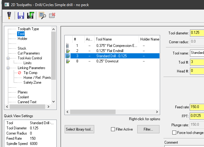
The Onsrud has a very specific tool library installed by staff/student staff. The tool numbers and associated settings are very carefully set up and
maintained, and the tool library file added to this software has to be kept current to match. We do this regularly throughout the school year - there
will be one small difference between the tools listed and what we are using this week.
.125" drill bit is standard in the Onsrud tool changer. Unless we note otherwise in the future, it is/will be tool #3. We're using this to clear the
interior corners of notches - "dog-bone" as it's commonly referred to. The round tools cannot create square corners, so this is a simple way to make
space for the square material (see images below).
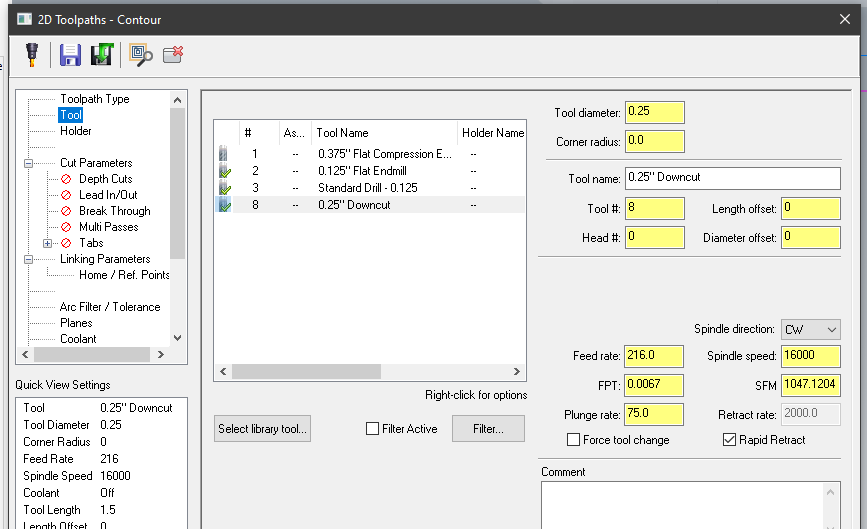
.25" downcut is a standard - we have temporarily switched it with a .25" compression end mill for this assignment.
the .375" compression end mill is an option for cutting very slightly faster, but should not be used for small/delicate details. We will usually use the .25".
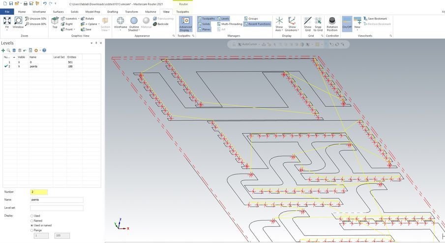
The geometry we need for these files are clean 2D curves and points for drilling. Drill points should be added ahead of time in CAD.
Please draw these points (actual points - NOT tiny circles) in a separate layer, for all interior notch corners (this creates the 'dogbome').
You might have a lot of these, and drawing in Mastercam is not efficient.
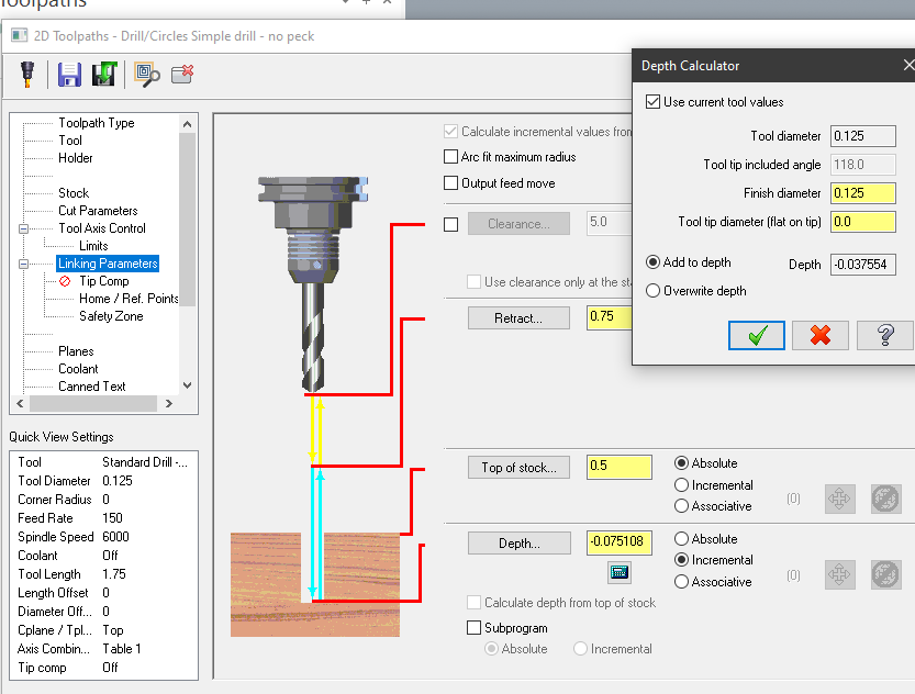
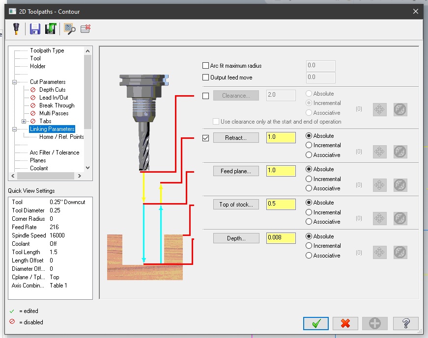
Drill toolpath defaults are fine - but we clicked on the little blue depth icon in the Linking Parameters to have it compensate for the shape of the
drill bit's tapered tip. Those default settings are fine. Make sure it's on "overwrite" rather than "add". The depth should be just enough for the
taper at the tip of the drill bit to clear the material, and nothing more.
In the contour toolpath, we're using either a .25" tool - #8, or a .375" (#1). #8 is called 'downcut' on the library, which is what is normally
installed there for the rest of the semester, but we've switched that type out with a 'compression' type for this week.
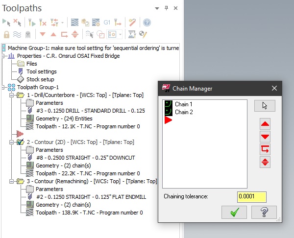
For curve-driven toolpaths like this, you select curves one at a time- click once on each closed curve to add them to the geometry to cut. In Mastercam, they're
called 'chains'.
Notice that a direction arrow will appear - they may not all go the same way. When the toolpath setup is finished, some may be
offsetting to the wrong side of the curve because of this -
you can right-click on 'geometry' and find those backwards chains, and 'reverse' them one at a time to fix that.
We turn off Lead In/Out for these contour paths- it isn't necessary here.
In the Contour's Linking Parameters, setting Retract and Feed plane to an absolute 1 (inch) tells it to raise the tool 1 inch in Z between every non-cutting
horizontal move. On routers, safe retract and travel heights in Z are extremely important to pay attention to in toolpath setup, as well as Z depths. This
will require more attention in the molding/casting assignment in 2 weeks.
In the current template file, we are doing 1 stepdown for the contour cuts - that means it does not plunge all the way down to the onion skin depth on the first pass.
The Depth setting is where we leave some Z height for that onion skin. In the attached file it's currently set to .008 (absolute).
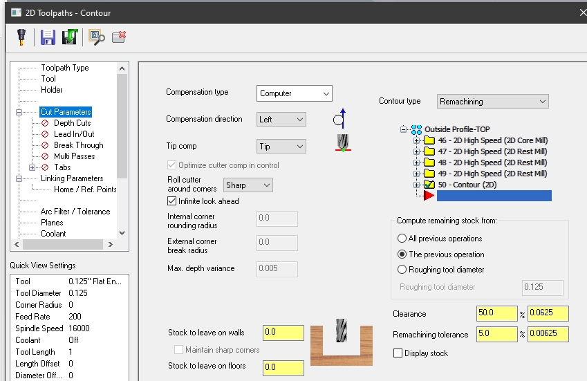
The Contour remachining toolpath is copied/pasted from the original Contour toolpath - it's meant to go back and clean up just what material is left over from
the previous cut. The interiors of the notch corners have little wings left by the .25" diameter of the compression end mill, and we need to remove those to
make the notches rectangular.
The template is using tool #2, a .125" up cut, which is the same diameter as the shanks of
the tools you've been putting into the Modelas recently. It's small and delicate, so we only use it to clean up small traces of OSB. Attempting to cut through
solid material with .125" tools just breaks them.
Note in the screenshot above that there's a set of "compensation" lines - these refer to the tool offset.
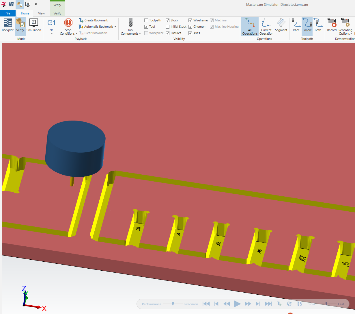
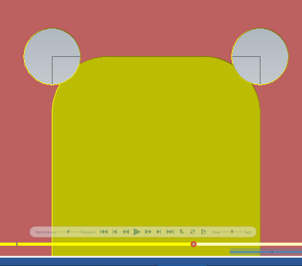
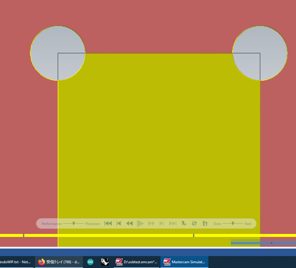
In the screenshot below, you can see the small blue lines in the notches that only appear in the interior corners - those are the remachining path. The pink
lines are imported CAD geometry (those numbers were just for visual reference, not for cutting).
The blue lines are cut lines, and we can adjust which ones are visible or invisible for easier viewing when they get
cluttered.
Yellow lines are travel moves, which must always be safely distanced from the material.
When toolpaths are set up, you can preview them separately or together.
Above is a closeup of the result of just the .25 tool contour cut and the drill points. Not yet rectangular.
And then above is the same notch after the 'remachining' toolpath.
I have added a small pocket to the template file to demo what we need to do for small cutouts. That toolpath can be run
with the rest of the test, or left out, as it's unrelated to the press fit situation.
For large pieces, it's
fine to cut them with the same contour (outlining) toolpath as the exterior shapes. But small pieces get knocked loose too
easily, and I've seen tiny one get compacted between the end mill and the edge of the pocket, which disrupted the whole chipload
process and heated up nearly enough to start a fire. So for smaller cutouts (say anything less than 4x4 inches, though we can
decide on a case by case basis), we need to cut them out as 'pockets' instead of contours. You'll see that this type of toolpath
removes the entire volume of the pocket, starting at the center and working its way out. It uses the same settings, otherwise, as
the other toolpaths, which for OSB press fit jobs, are mostly just outlines and drilling/cleaning up interior corners.
 RESERVATIONS
 HOURS
HOURS TUTORIALS