Molding & Casting, HTMAA-style
Dropbox = Intelitek
tool library and CAD/CAM examples will be added/updated here
Your assigned material: one block of machineable wax @ 3x6x1.5 inches, Oomoo 25, and Hydrostone/Drystone gypsum-based casting material.
The constraints: everyone must cut a 'positive' into the wax- 1 or 2-sided mold. Tool geometry must be included. Then pour Oomoo silicone into the wax to
make a 'negative' in which to pour the third material, a type of plaster.
This is an intentionally specific set of steps for the materials for this week. Please keep in mind that this is not meant to be
the one and only correct way to mold/cast- it does maximize experience in a
small package, and without necessarily requiring super-expensive software or machines.
You may want to try larger, more complex,
different types of molding and casting, including other materials, and that's great - but materials provided to each student for this week are very
specific, so even if you have previous casting experience, please work with these for the assignment. The constraints
peculiar to this setup can still be an interesting challenge to those who have done other kinds of molding/casting.
Once you have done the required process, then you can progress from there.
If you advance beyond Oomoo/plaster,
Do Not Forget that other liquid chemicals must be approved and used under
supervision of shop management in our space - do not ever bring in other casting plastics or 2-part liquid chemicals without contacting us first.
I've saved several samples from previous years so you can see some of the details you'll be focusing on. They'll be out on the table
in 3-412 by the Intelitek over this week, and I can pull them out for scheduled training groups.
There is a
significant limit to what can be squeezed into these little volumes, especially considering
the different parts that need to fit inside (only one of which is going to be your finished object),
and also the widths of the end mills also needing space to move around between
all those parts.
You're not just designing an object - you're designing a tool to use to make an object, and the tool needs to fit inside a fixed volume-
and the tool's features require space of their own. Keep these size limits in mind while coming up with your designs.
I've taken a lot of notes to help you stay within the boundaries- illustrated in the relatively dense toolpath setup -
please check all details carefully.
We have several machines that are capable of 3-axis milling. For the scale we're working at this week, the Onsrud is
not ideal. We have the Intelitek (in 3-412), the Prototrak (in N51), and the Shopbot (in 3-410). The Modelas are also
capable of 3-axis milling using Mods, but are by far the slowest of the bunch.
We use Mastercam to set up toolpaths for all these other machines - they should be found under the machine navigation menu. If a
computer has only been used to set up Onsrud files for a long time, the machine setup for the others may not have been fully
installed. The files are available on this site (software page), and need to be copy pasted into the correct folders - then in
Mastercam they need to be added.
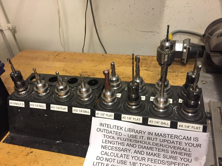
Only the Intelitek and the Onsrud have preset tool libraries (saved as machine-specific tooldb files). The Onsrud has its automatic
tool changer - which is a lot of work on the part of shop staff/TAs to maintain so users can just pop in and use them without more
setup. The Intelitek has a set of tool holders set up, but they still need to be inserted/removed from the machine manually.
The Shopbot and the Prototrak need tools installed completely manually, each time. For those we just use a generic tool library.
The Intelitek is a good size for a machine for a job like this. It's got a mini tool library set up, which is convenient as long as it's
used correctly. It's not an automatic tool changer like the Onsrud, but there is not too much manual work that needs to be done to change and verify tools.
There is an Intelitek tutorial page on the shop website, geared towards this wax assignment. There will be a current Intelitek.tooldb
(tool library) file in the Dropbox, as well as the Rhino/Mastercam drawing that I have set up as an example.
It's more complex to set up a template for 3-axis jobs - I've made my Mastercam file as universal as possible, but depending on the
object that you draw, you definitely might want different finishing toolpaths to get the best results. We will have to go through this with you unless
you have a significant amount of previous CAM experience.
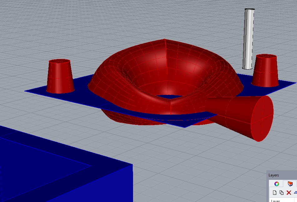
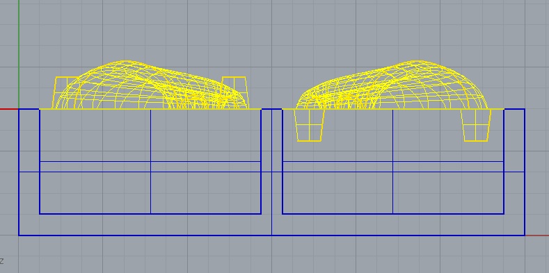
The Rhino drawing I set up as an example has a model of the wax block with maximum space hollowed out,
while still leaving .25 inch walls. It's possible to eke out a bit more from the walls, but not much without risking cutting
through them. The wax blocks are cut on a band saw, so not all edges are perfectly straight.
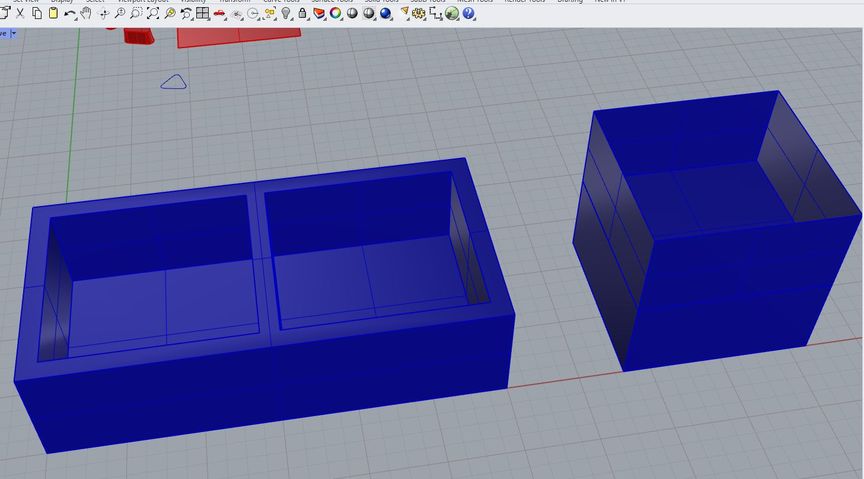
I've copied the interior space and pasted next to the block, just to show a positive representation of the bounding box that
we can work within - if you eliminate the wax walls, they can be a little bigger, but then you have to build (hot glue chipboard?) walls yourself to
contain the Oomoo with a watertight seal.
Remember that this negative space must fit the Oomoo mold with its registration marks and sprue, enough breathing room for the tools to move around in
to cut the parts out (remember that tiny end mills have very short cut depths and that for any deep cuts in these, our smallest endmill is usually going to
be 1/8 inch diameter), and the even smaller piece - the object being cast.
Modeling for CAM setup is not like modeling for printing.
Do not make your objects meshes- we do not want polygon surfaces here unless there
is no other choice. If you have a scanned object, use the template or draw NURBS surfaces to create the rest of the wax geometry.
Material geometry is necessary for CAM setup, especially for us here because we are using part of the wax block, left behind, as part of the tool.
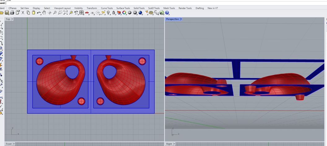
On the left in the screenshot above is the view from the top. This is what the 3-axis machine can 'see' from above and can conceivably reach with the edge or tip of existing
tools if we've designed with their sizes in mind.
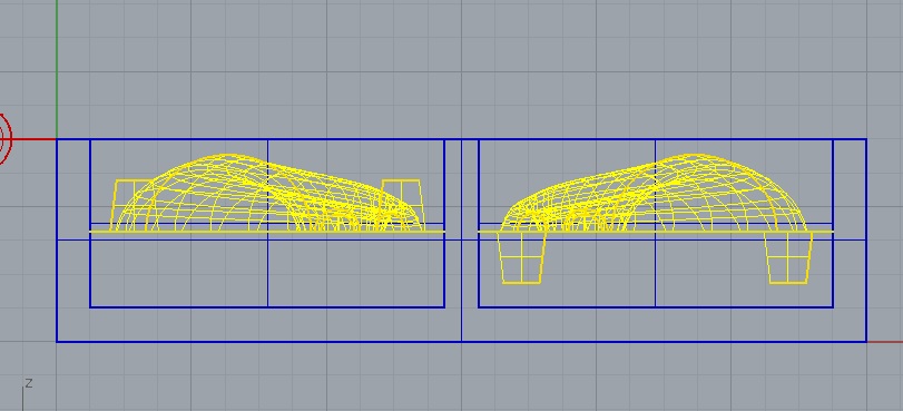
The right side of the previous screenshot and the next screenshot are the
same drawing seen from the side/below.
The dimensions and locations of the wax geometry are still exactly where they were drawn to accurately describe the material block, but I've deleted
all the unnecessary vertical and hidden surfaces. I've also added curves (yellow) that we will need in some
places to tell tools where to cut to clean up edges. If we only have surfaces to refer to in toolpaths, the edges will often not cut clean - depends on
the geometry and the toolpath pattern.
If you make a 2-part mold, it will be simplest if you can split your model with a simple
2D plane so the 2 halves of the silicone molds will have flat mating surfaces.
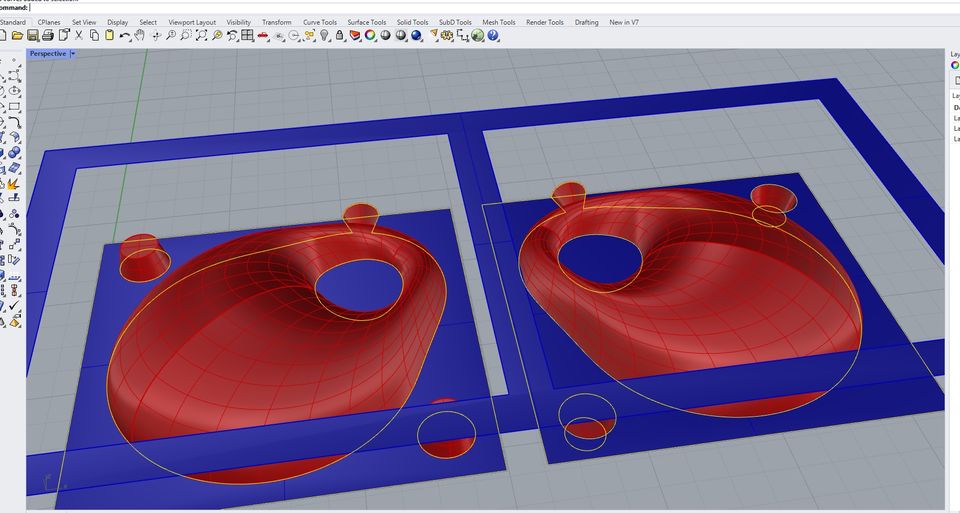
I drew a .125" circle which is the width of our smallest end mills on the various routers - just to have an
easy visual to show how an 1/8 inch tool fits (or doesn't)
just well enough to be able to cut along one edge of an object, and still shift over a tiny bit to cut the
other side. These toolpaths will insist on having a little more than the diameter of the tool to move within,
to cut in these types of situations.
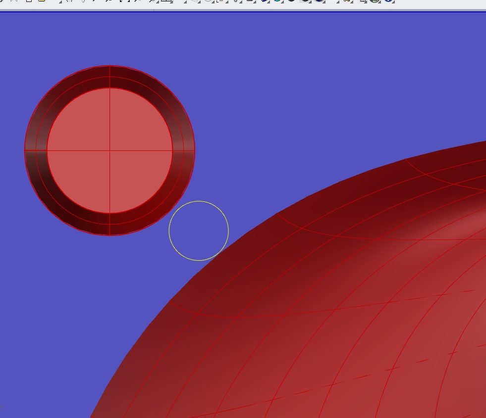
If your tool is .125", you cannot easily force it through a space that is exactly
.125" wide. There are ways to try to deal with that, but require extra modeling steps that we would be better off
avoiding this week, considering the long list of steps required to get this assignment done in a week.
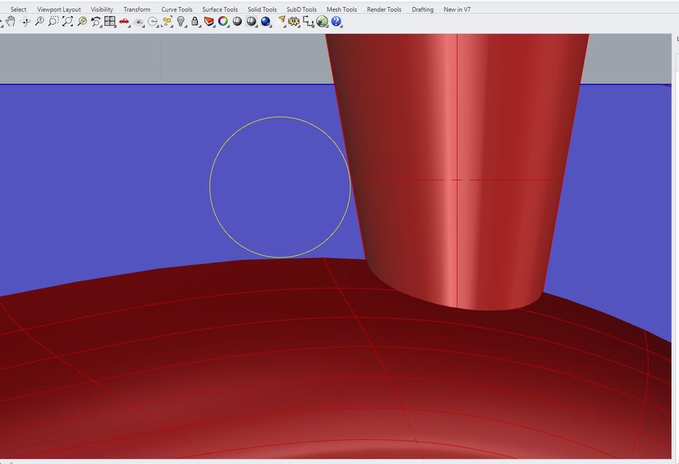
Also, see how the curved side of the tool won't fit into the sharp corner between the 2 objects? Remember that when
we mill out the wax (see samples for this kind of detail), sharp interior corners like that will be
rounded. The best thing to do is attempt to model something with as few details like this as possible for better-looking
results.
What to consider when modeling for 3-axis Milling for this assignment
I've got samples of some previous years' projects saved on the table by the Intelitek in 3-412.
Do not convert your file to an STL - send a 3dm, step, or other NURBS model type., Meshes are more difficult to work with in CAM.
There are some important details to take note of when looking at these.
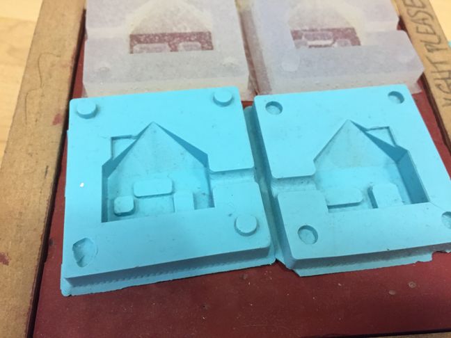
The geometry should be recessed low enough that when you pour the silicone, there's a decent thickness at
what will become the bottom of your negative.
Pick up the silicone samples in 3-412, and check out the really thin
'bottoms' on the house molds, where the negative shape of the house comes very close to that face.
Students tend to either draw their models a little too close to the upper surface of the wax like these house models, or further
down than necessary.
Here, I moved my 2 halves down from the tops of the boxes to leave enough space for decent silicone thickness
without going further than necessary. The original blue box was just for reference before I decided what object to model
- I didn't plan on cutting all the way down to .25" Z unless my object made it necessary.
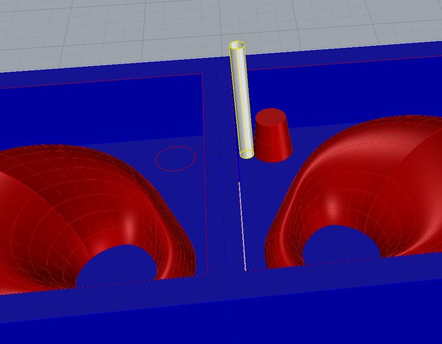
I drew especially tall registration marks which got reduced to a more efficient height in the final Rhino file - because they are positive
and negative spaces that must fit together cleanly (almost like legos but not quite so tight), they need toolpaths to clean up their
sides as well as the sides of the outer walls of the boxes, to clear out that narrow space between them without shredding or otherwise making a mess
of anything. If your model requires tight spaces like
this, it might be okay- just keep in mind that we do have minimum tool sizes, and more fussy details will mean more fussy toolpathing.
Good experience, but takes time.
A file that can be used for reference, and possibly somewhat of a template, is uploaded to the Dropbox.
There are a lot of details in there - I did screen capture of the process, but editing the video may
take time that we don't have right now. There are many toolpaths - here's the general breakdown-
The first 2 are roughing toolpaths - they take out excess material from each side. You could lump both
sides into one toolpath, but this way is quite a bit faster. Step downs and overs have been adjusted,
and I had to compensate to 'inside' to keep the tool inside a containment boundary, which was just a
rectangle I drew duplicating the edges of the interior. A lot of surfaces edges sometimes get duplicated
(in CAD) to make referencing their edges much easier for things like this.
I left a bit of material on the 'drive surfaces' so that the finish toolpaths would have something to
remove - leaves a nicer finish surface with fewer millmarks.
The next one is a contour that does stepdowns around the inside border to clean up excess material that
I don't want to risk plowing through with a finish toolpath, which could overload the tool with too
much depth + width all at once. This adds a tool change, because I want to use a narrow tool, but I'm
setting this up for the Intelitek, so it's not too difficult to switch between them.
The next 2 are constant scallop (surface finish). I reduced the stepover even more to get nicer finish,
and an important thing to notice on these is that check surfaces are important as well as containment boundaries,
for telling the tool where
not to go. Look carefully at containment boundaries (curves) and check
surfaces (surfaces) on each toolpath - I think I used them on every single one.
To get relatively clean edges on those tapered pegs (and their pockets), I had to use 'flowline' to get
the tool to cut in circular passes that stepped down. This is much easier in a pocket toolpath if you aren't
also trying to cut a taper, just using a ball end mill. I didn't need to do this, but I have a tendency to
taper things. There are 4 of these, one for each, because I couldn't get the offset to stay consistently
on the insides when I tried to group them together in one toolpath.
The last 2 were an attempt to clean up the funnel surfaces, which just seemed messy to me. The connection
between them and the ring in the center didn't look good. It's not the kind of connection that an 1/8"
diameter tool can really make nice, but this helped a tiny bit, at least.
Silicone and plaster handling
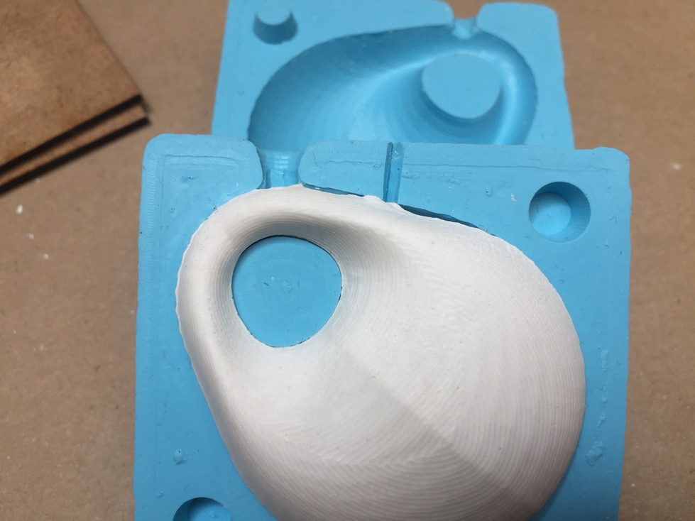
The silicone is floppy and distorts easily, so when you're working with it to cast the last step, you want to
be able to gently press the 2 sides closed (using those cleanly cut registration marks to locate them correctly) without warping anything.
The super-thin outer wall distorts easily.
The outer wall, as you can see, is created by your pour. Oomoo is very flexible, so models without 'draft angles' are
possible, though vertical walls can be difficult to remove. Oomoo also cracks pretty easily if it's stressed much, so don't expect
to do a lot of stretching and pulling with it and have it survive.
There's a sample of a really lumpy, messy pour in 3-412, along with
several clean ones.
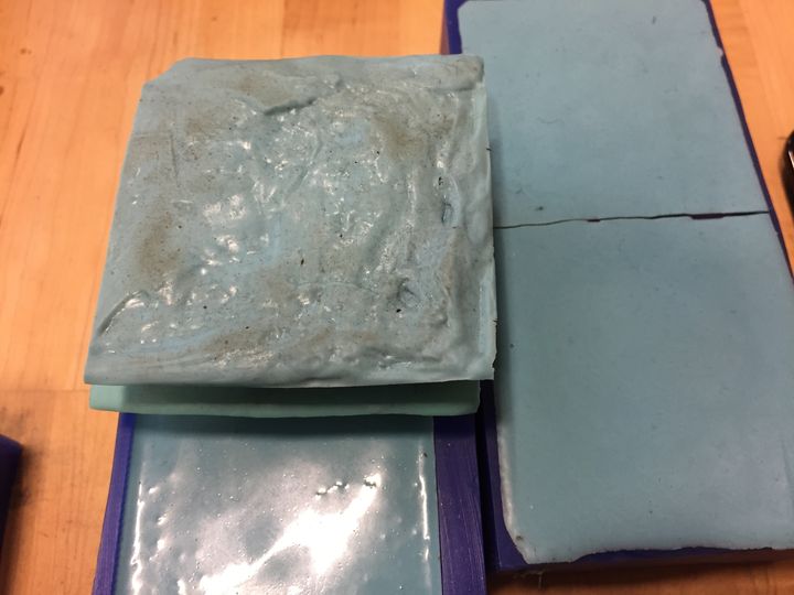
Imagine trying to press 2 of these together with even clamping pressure. If the outer surface is
lumpy and uneven, you won't be able to put even clamping pressure on that area without distorting the silicone
piece.
The lumpiness could have been caused by expired material, or material left
sitting around too long to the point where it started to cure.
We have paper cups/wooden stir sticks for mixing Oomoo - WEAR GLOVES, and take the time to scrape the sides and bottom to mix the 2 parts
as thoroughly as possible. Some bubbles will happen, but try not to fold too much air into the liquid.
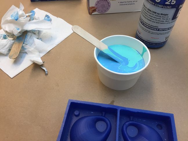
Fill the 2 sides to the top, but not past it - we need to tap the box to vibrate the bubbles out, and the tops need to smooth
out without spilling.
Please do your best to spill as little as possible. This stuff does not wash off with soap, destroys clothes, and will not dry on its own. It requires
solvents for cleaning (which does nothing but dilute it temporarily) so please work as carefully as you can not to spill. Smears of Oomoo
do make the work more obnoxious, as well as very difficult to clean up.
This means that even though Oomoo is not actually toxic, you do not want to get any on your hands, clothes,
the floor, or other places other than that (6-8 foot long) piece of brown paper.
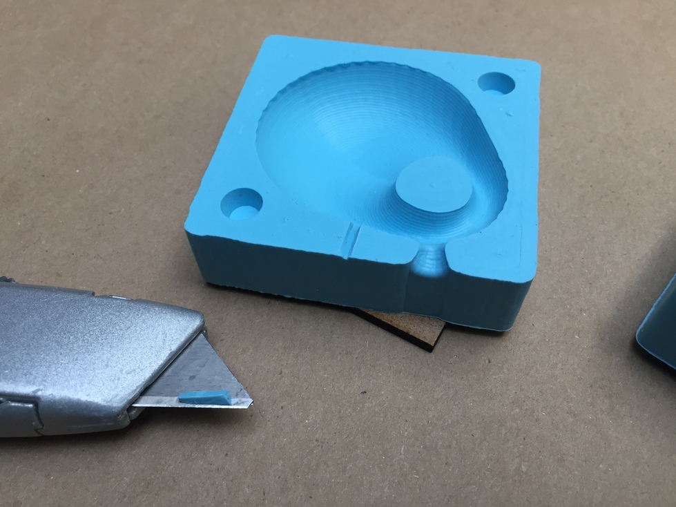
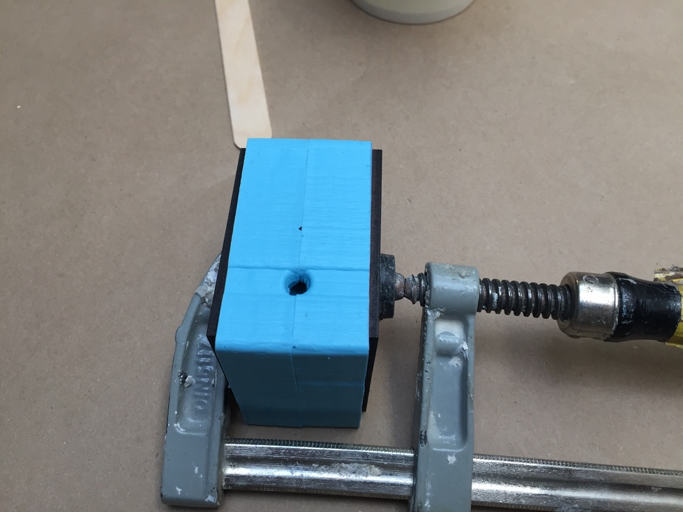
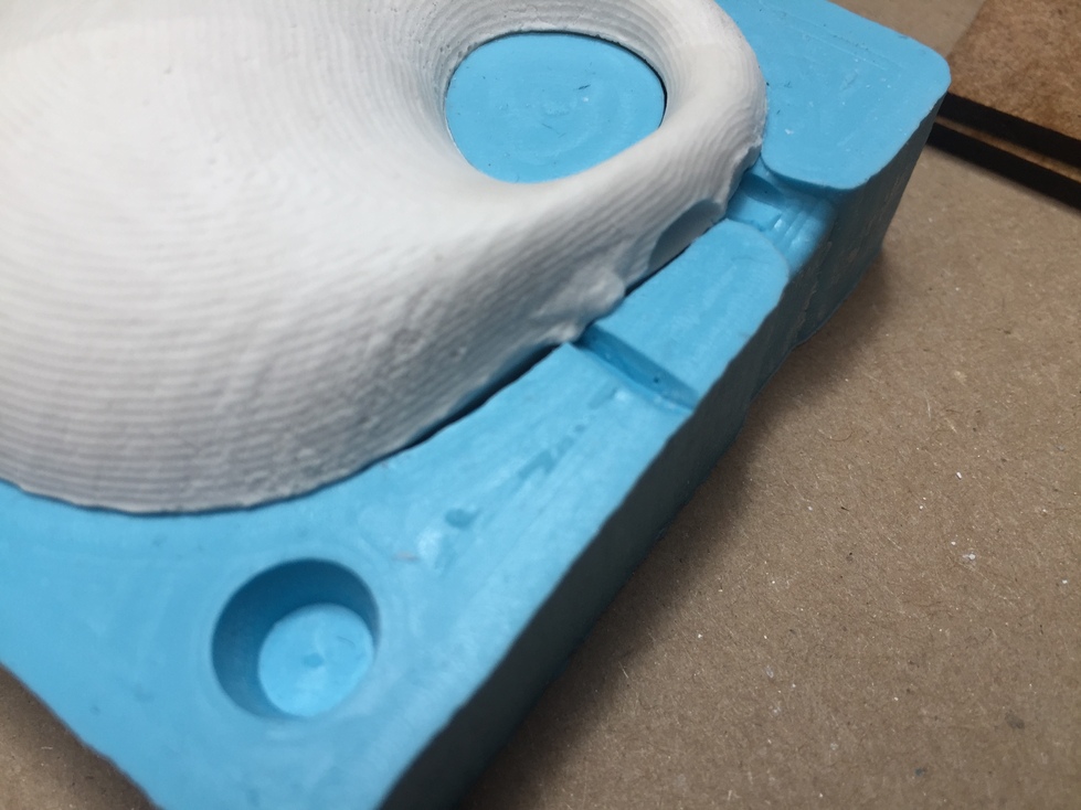
Once the silicone was cured, I cut a very narrow channel on one side of the mold, just to allow air to escape, just using a utility knife.
These can be pretty tiny, so it's much easier to just cut the hairs-thin notch with a sharp knife than to try to model.
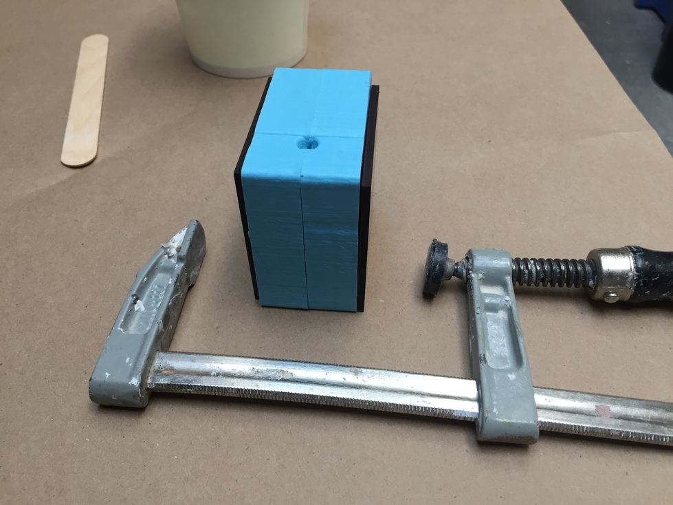
I cut a couple of squares of Masonite to make it pretty simple to put gentle but
even clamping pressure on the
sides of the mold. Otherwise it's like pinching a sandwich with two fingertips - you'll compress under the clamp, but the rest
will just bulge out- which is not going to work. This may sound obvious, but I've seen it attempted.
Now to attempt pouring a plaster mixture into this -
There is a ratio of water to powder (by weight) listed on the Hydrostone packaging - for this little test, going along with what
the majority will want to do for this assignment, I just eyeballed proportions to see how it would go -
which is still more difficult to do efficiently than it seems. You don't want to waste material, but managing a pourable
consistency is a fairly small window to aim for.
It meant that after I scooped what would be a small handful of powder into a paper cup and added just a splash of water, the
mix seemed too thin. So I added a couple of teaspoons of powder, which made a passable pouring thickness.
If you spend too much time going back and forth with this, you'll end up with a lot of wasted material, and it can even start to cure
while you're still trying to mix it.
So in my case it worked out, but I did have more extra waste than I really needed to make.
It's maybe acceptable enough for tiny pours like this, but for large projects it would
not be - it's extremely important to calculate
volume and actually measure your parts on larger casting projects.
 Also -
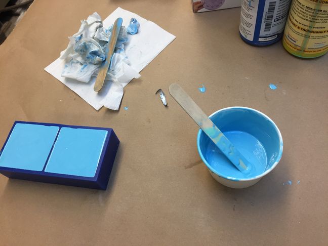
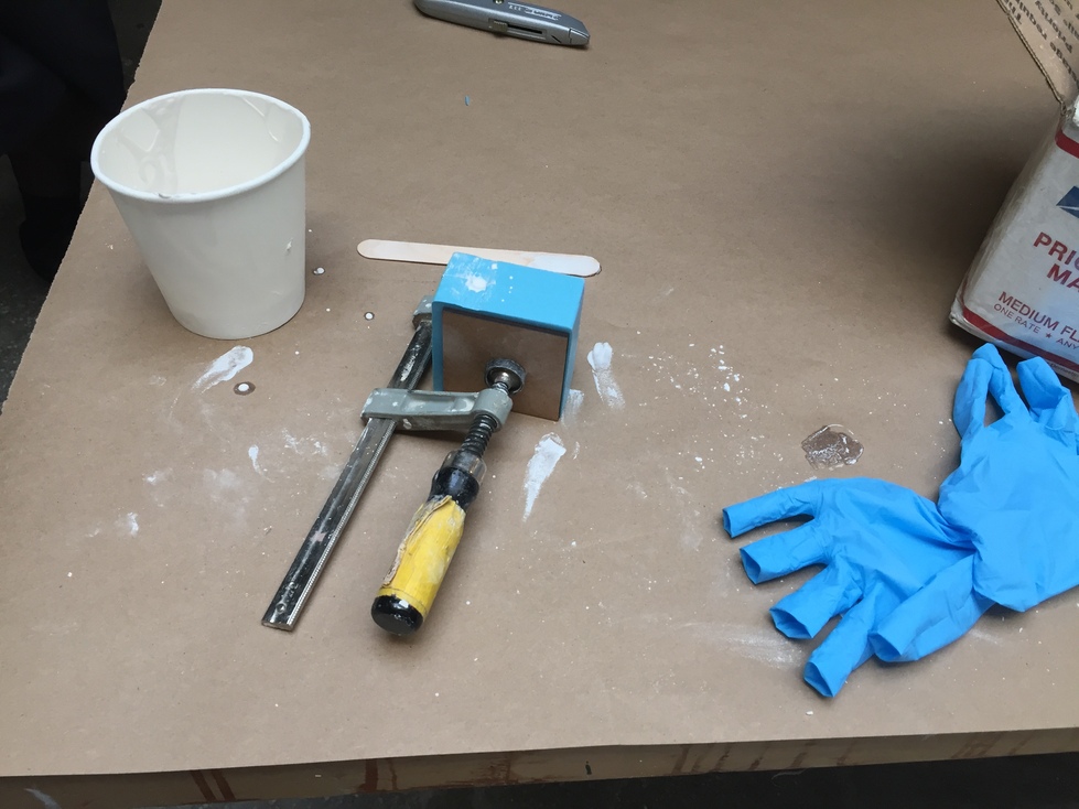
 see how much mess is created by such a tiny casting? This is an example of how even very careful work makes
a mess that proves you need to really cover the table to protect it.
Leave the mixing cup/stick out to cure; once it's hardened, it should just be tossed
into the casting scrap bin.
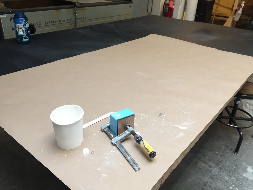
This is why we insist that you always use a LARGE piece of brown paper to do any messy work on. I was being careful and I
still managed to spill a bit of plaster powder over 2 feet away from the corner of the table. PLEASE do not try to do this
kind of work on small bits of paper. Rip off at least 4-5 feet length pieces, every single time.
Video of the slow process of pouring into that tiny sprue and frequently tapping the mold to clear it will be uploaded...
Not yet pictured: I had to pour a little at a time and tap the mold very frequently, because the tiny sprue kept clogging - the air hole
helped somewhat, but the thick mixture and the small hole just don't play well together. If you have a tiny opening like mine,
expect to pour maybe a spoonful at a time; it will suddenly clog and threaten to overflow out on to the table,
when you'll have to stop to tap it to clear the sprue.
The silicone and the plaster will pick up on the tiny mill marks left behind in machining.
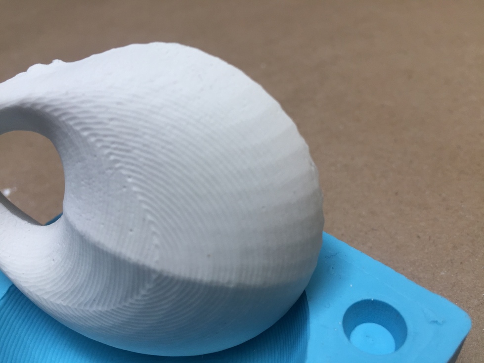
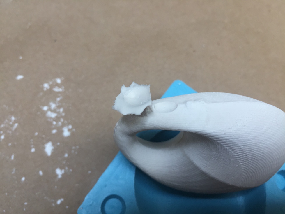
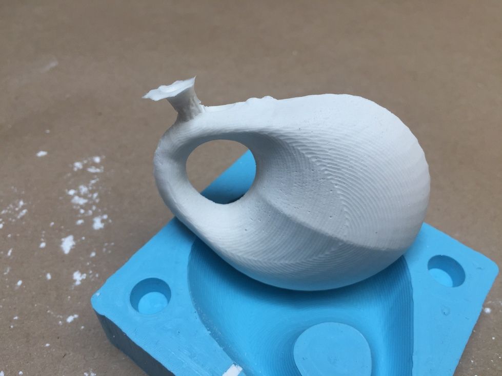
I snapped the sprue off before replacing the casting in the mold to check out the edge quality issue -
There is a little airspace I didn't manage to fill, despite a very thorough attempt at pouring and tapping out bubbles
Even though I really tried to patiently pour and tap the mold to entirely fill the space, I think the problem was that
my top surfaces were too near horizontal,
which left some space that visibly didn't fill even when the sprue and airhole finally filled with liquid. This is a good
thing to keep in mind when you're designing your mold, so you can minimize issues with air pockets (and also avoid an ugly
break point for the sprue if there's a less visible location for it). I put the sprue in this location because my vague plans
involved wrapping rope around the narrow end, which would hide that ugly spot.
 RESERVATIONS
 HOURS
HOURS TUTORIALS